
Insulating concrete form (ICF) system with tie member modularity

a technology of modularity and tie members, applied in the direction of forms/shuttering/falseworks, walls, shaping building parts, etc., can solve the problems of one type of block, inflexible design, use and implementation of icf tools used to form the connecting tie members, and inability to offer a more modular system, etc., to achieve flexible and flexible modular tie, promote efficiency, and promote flexibility and modularity

Active Publication Date: 2014-09-18
ICF MFORM
View PDF4 Cites 20 Cited by
  • Summary
  • Abstract
  • Description
  • Claims
  • Application Information

AI Technical Summary

Benefits of technology

The present invention relates to a new type of foam block configuration that can be easily stacked and connected together, allowing for the creation of walls with different widths and heights without the need for separate tools or costly manufacturing processes. The foam blocks have alternating teeth and sockets along their edges that enable them to be securely connected together. The invention also includes a tie member that can be used in any of the foam blocks, allowing for the creation of more complex and custom block designs. The interchangeable brackets and modular capability make the invention a cost-effective and efficient solution for the production of walls in different sizes and configurations.

Problems solved by technology

Due to the high capital costs required to make the molding tools for both the tie members and the ICF blocks in multiple widths, ICF companies have not been able to offer a more modular system that offers a standard line of ICF blocks in multiple heights as well as multiple widths.
Currently, besides being costly, the ICF tools which are used to form the connecting tie members and the opposed block panels are extremely inflexible in their design, use and implementation.
As a result, once a particular ICF tool is hung for use, it can only make one type of block, for example, a straight block in only one width.
Having to switch out tools in this matter is time consuming and costly for two reasons.
First, it currently takes most ICF manufacturers an average of several hours to unload one ICF block tool and hang another tool.
This reduces the number of ICF blocks that can be produced in a particular day on a particular machine and therefore increases the respective costs of those blocks actually made.
Secondly, each ICF block tool that is hung can only make a certain number of ICF blocks in each forming cycle.
As a result, because of the costs involved in purchasing all of the various tooling for providing a full line of ICF products having different widths and heights, most ICF manufacturers only provide the most common and highest volume ICF block widths and heights.

Method used


Image

  • Insulating concrete form (ICF) system with tie member modularity
  • Insulating concrete form (ICF) system with tie member modularity
  • Insulating concrete form (ICF) system with tie member modularity

Examples


Embodiment Construction

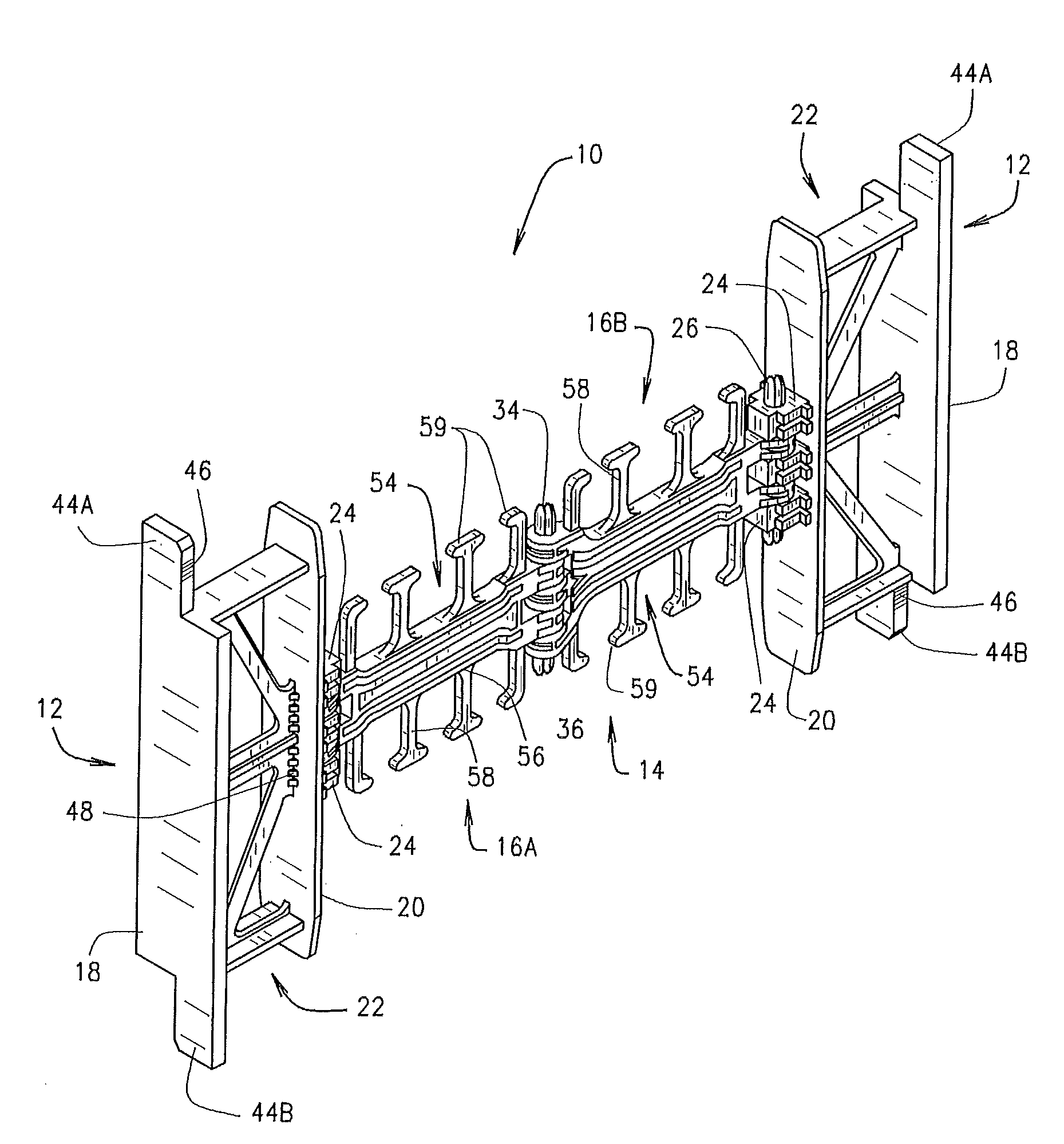
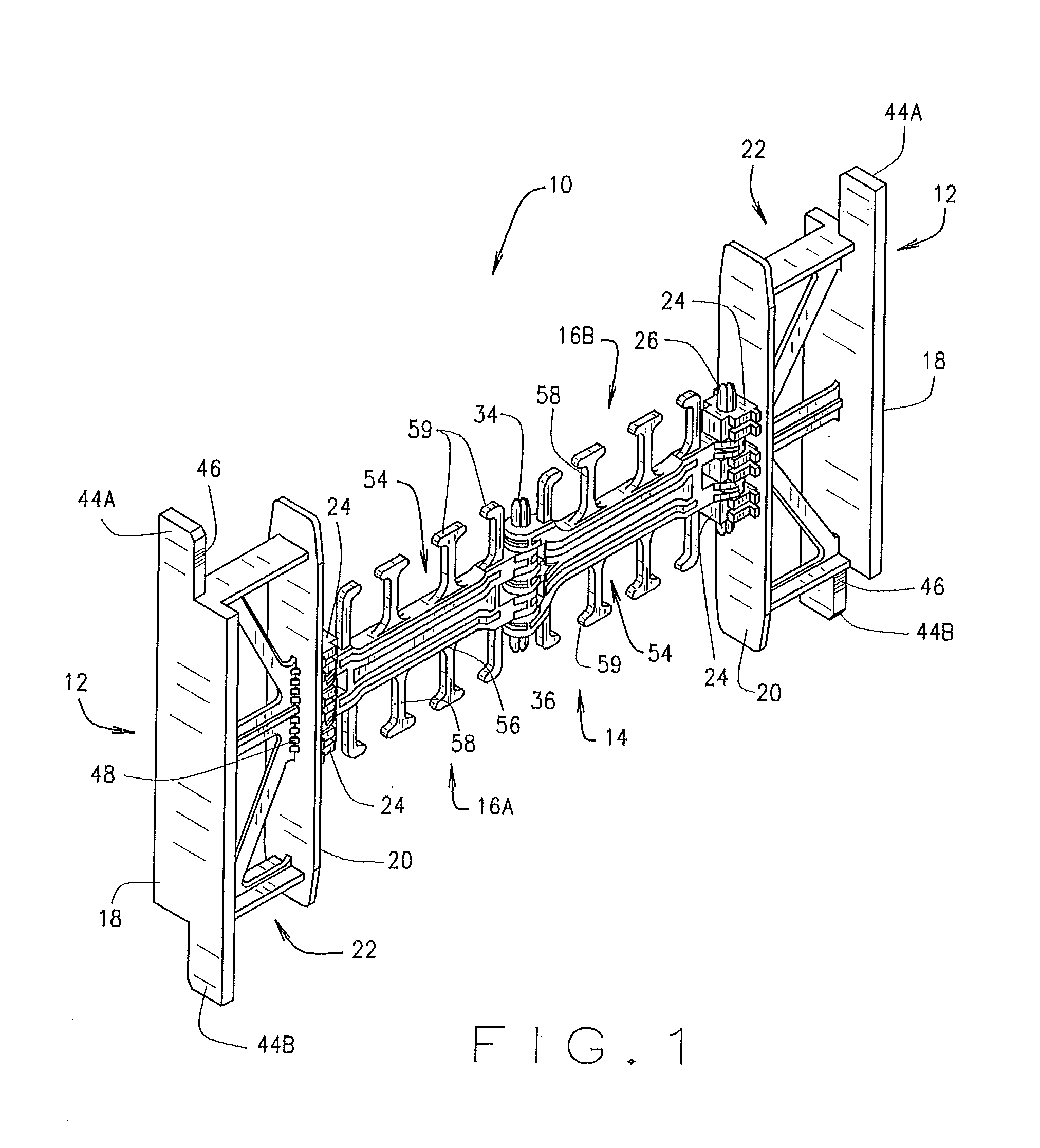
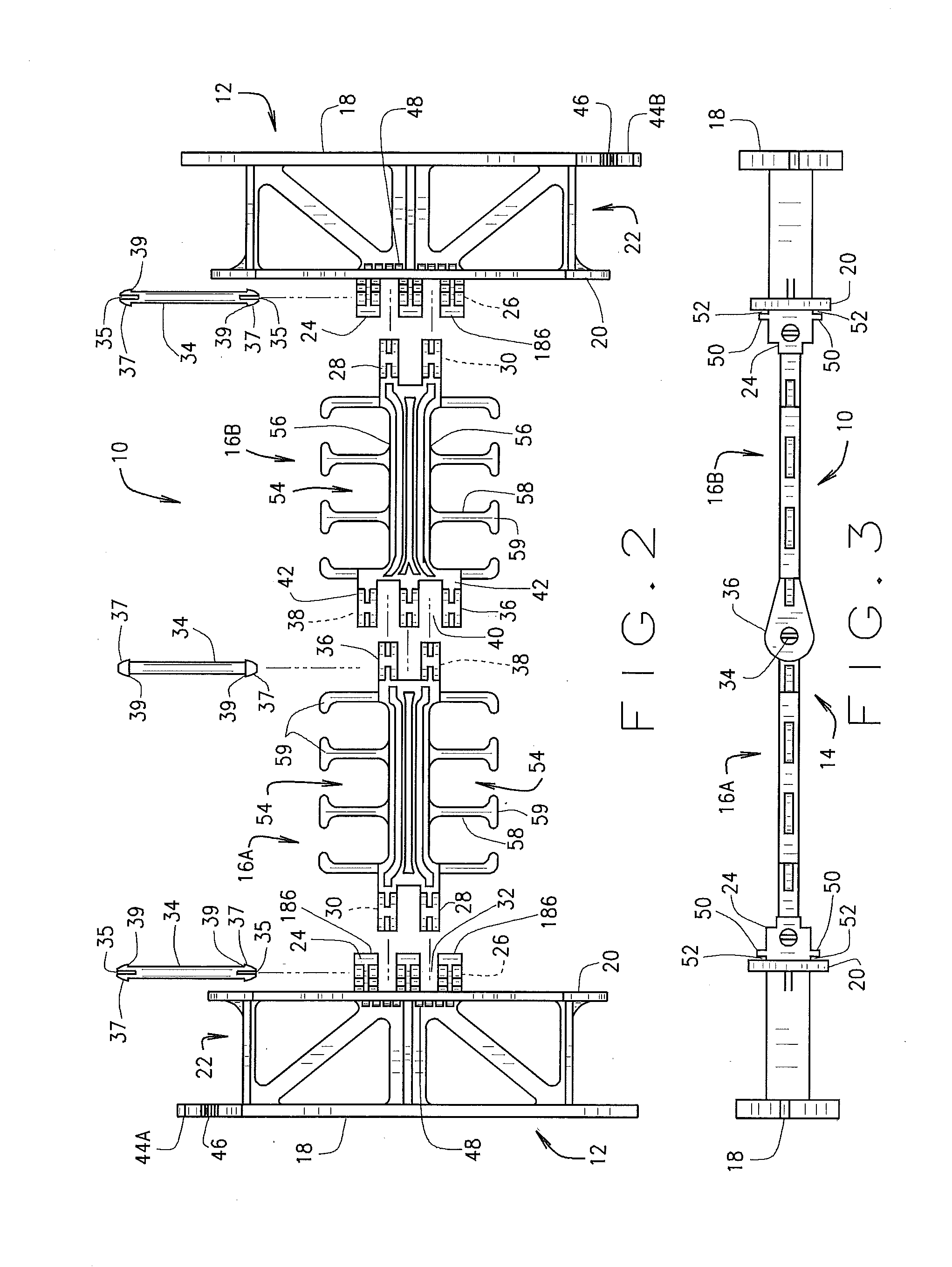
[0057]Referring to the drawings more particularly by reference numbers wherein like numbers refer to like parts, the numeral 10 in FIGS. 1-3 identify one embodiment of a stackable / foldable spacing tie member constructed according to the teachings of the present invention. Although use of the present tie member 10 will be discussed herein in relationship to a substantially planar or straight ICF block, it is recognized and anticipated that the present tie member 10 can be utilized with a wide variety of different types of ICF blocks including a 90° corner block, a 45° corner block, taper top blocks, ledge form blocks, and so forth. As will likewise be discussed herein, it is also recognized that the present tie member assembly 10 constructed according to the teachings of the present invention can likewise be fashioned into a variety of different sizes and shapes other than those illustrated herein without departing from the spirit and scope of the present invention and that the other...


PUM


Abstract

A modular tie member which promotes flexibility in manufacturing ICF blocks of varying widths and heights, one embodiment including a pair of side wall bracket members each encapsulated within a respective panel member forming an ICF block and a web member pivotally attached to and extending between the side wall bracket members. Each bracket member may include an extension portion and / or another interlocking mechanism associated with each opposite end thereof positioned for overlapping and engaging similar members associated with similarly constructed tie members when one tie member is stackably arranged one on top of another tie member. The extension portions and / or the other interlocking mechanism extend into respective teeth associated with the horizontally opposed edges of the panel members for mating with the extension portions and / or the other interlocking mechanism of another tie member associated with a similarly constructed ICF block positioned in vertical arrangement thereto. In still another embodiment, the web member is a one-piece member which is slidably engageable with the pair of bracket members thereby allowing the ICF blocks to be field assembled at the construction site.

Description

BACKGROUND OF INVENTION[0001]The present invention relates to Insulating Concrete Form (ICF) Systems utilizing foam block forms or other forms made of other comparable materials and, more particularly, to improvements to the ICF panels and the interlocking connection means associated therewith thereby achieving product modularity with respect to ICF block forms having different heights and widths.[0002]Insulating Concrete Form (ICF) Systems are well known in the industry and serve to both contain fluid concrete while it solidifies and provide insulation for the finished structure. Such systems utilize a plurality of individual units, panels or blocks aligned horizontally and vertically in an interlocking arrangement to create forms for concrete walls. Each block comprises a pair of panels which are retained in a spaced relationship parallel to each other through the use of a plurality of spacing or connecting tie members. As the ICF blocks are stacked, steel rebar rods are inserted ...

Claims


Application Information

Patent Timeline
IPC IPC(8): E04G17/12E04G11/08
CPCE04G11/087E04G17/12E04B2/8635E04B2002/8694E04G17/0758
Inventor PFEIFFER, HENRY E
Owner ICF MFORM
Learn More