Self-centering skate holder

a self-centering, skate technology, applied in the field of skate holders, can solve the problems of large and bulky apparatus, large and bulky design, and the location of the pivot axis,

Inactive Publication Date: 2006-06-08
SUNNEN AUGUST
View PDF11 Cites 1 Cited by
  • Summary
  • Abstract
  • Description
  • Claims
  • Application Information

AI Technical Summary

Problems solved by technology

Since the thickness of a skate blade may vary between different skate models and different skate types, this type of clamping mechanism does not ensure that the centrelines of the hollow ground and convex outer radius of the grinding wheel are aligned properly.
While this design achieves self-centering, the location of the pivot axis renders a large and bulky apparatus.
The user must guide the holder towards the grinding wheel, therefore a large and bulky design is not desired.

Method used


Image

  • Self-centering skate holder
  • Self-centering skate holder
  • Self-centering skate holder

Examples


Embodiment Construction

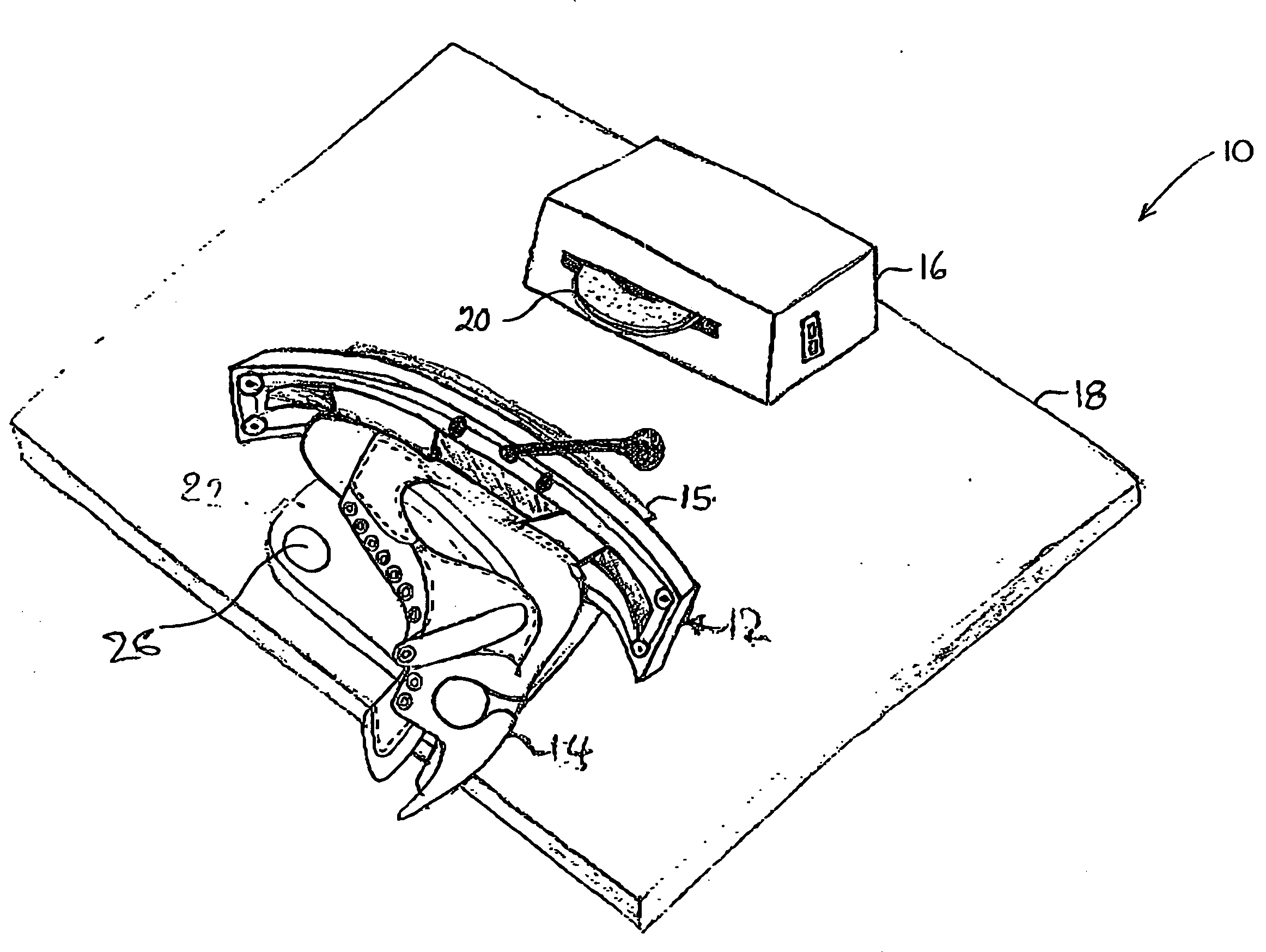
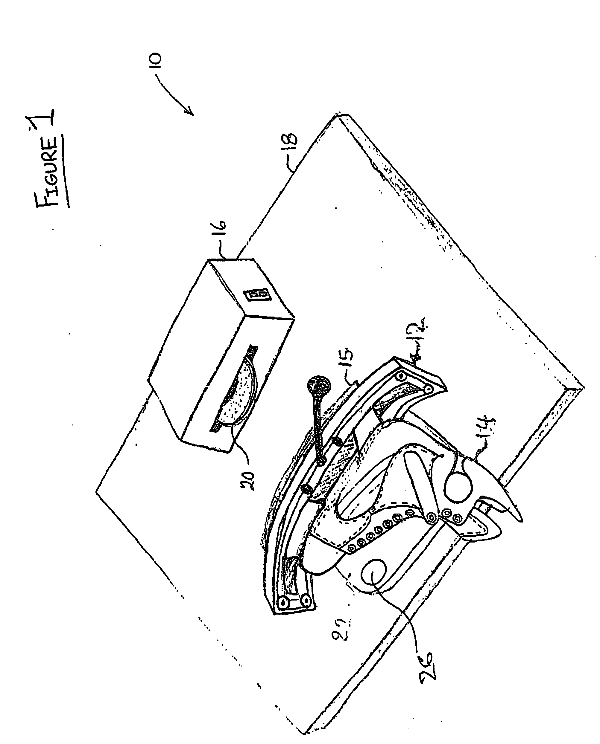
[0026] Referring therefore to FIG. 1, a skate sharpening apparatus 10 includes a skate holder 12 that supports a skate 14 having a skate blade 15. The holder 12 is slideable on a work surface 18 so as to be manoeuvrable past a grinder 16 having a grinding wheel 20. The grinding wheel 20 is positioned to rotate about a vertical axis in a horizontal plane and, upon engagement with the blade 15, to grind the requisite profile.

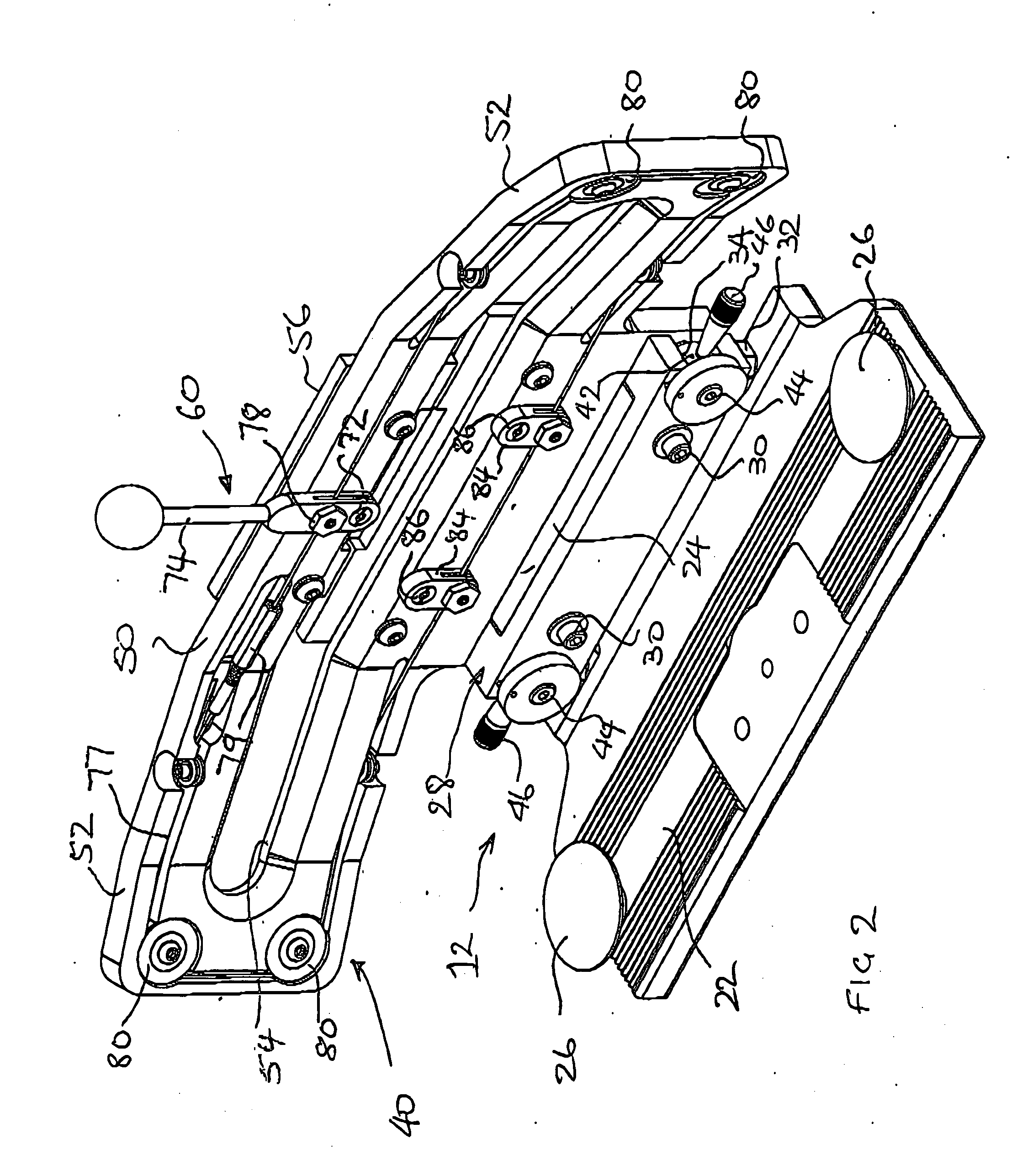
[0027] The details of the holder 15 can be seen in more detail in FIGS. 2 through 7. The holder 12 has a base 22. A pair of handles 26 are provided on the base 22 to facilitate manipulation of the holder 12 on the worktop 18. A mounting block 28 is secured to an upturned lip 24 of the base 22 by bolts 30. The position of the mounting block 28 relative to the base is adjusted by means of set screws 32 which are threaded into the base 22 and bear against the underside of the mounting block 28. The set screws 32 provide a nominal or coarse adjustment for the disposi...


PUM

PropertyMeasurementUnit
flexibleaaaaaaaaaa
movementaaaaaaaaaa
tensileaaaaaaaaaa

Abstract

A self-centering skate holder for clamping a skate blade from above and below which maintains the blade at a predetermined height and parallelism. A handle is connected with a cable which is taut and extends around the circumference of the upstanding vertical member. The movements of the cable activate cam levers which rotate cams that move a pair of jaws towards or away from each other. The simultaneous movements of the cams ensure that the jaws move in unison and through a similar distance allowing a skate blade of any thickness to be clamped along the desired centerline. In an alternative mechanism, a tie bar extends between the jaws and is operated by a cam to induce equal and opposite movement of the jaws.

Description

[0001] This application is a continuation-in-part of U.S. patent application Ser. No. 10 / 735,896 filed on Dec. 16, 2003.FIELD OF THE INVENTION [0002] The present invention relates to skate holders for use with skate sharpening machines. DESCRIPTION OF THE PRIOR ART [0003] Skates used in activities such as hockey, figure skating, speed skating and for leisure include a boot and a blade. The blade is attached to the bottom of the boot and is used to ‘dig into’ an ice surface allowing the skater to glide along the ice due to the opposing force imparted on the skater when pushing against the ice surface. To effectively grip the ice surface, the blade includes a concave surface at its lowermost edge. This concave surface, commonly known as a ‘hollow ground’, produces two parallel edges opposed about the centreline of the hollow ground. Through repeated contact with the ice surface, the edges are worn down due to friction with the ice surface and periodically need to be sharpened. [0004] ...

Claims


Application Information

Patent Timeline
Patent Type & Authority Applications(United States)
IPC IPC(8): B24B7/00B24B3/00B24B41/06
CPCB24B3/003B24B41/06
Inventor SUNNEN, AUGUST
Owner SUNNEN AUGUST
Why Eureka
Try Eureka