
Safety stirrup

a safety stirrup and stirrup technology, applied in the field of safety stirrups, can solve the problems of serious injury or even death, one of the feet of the rider can be caught in the stirrup, and the rider cannot be easily remounted, so as to overcome the disadvantages or overcome the disadvantages

Inactive Publication Date: 2006-06-15
ZILLMER PETER
View PDF8 Cites 4 Cited by
  • Summary
  • Abstract
  • Description
  • Claims
  • Application Information

AI Technical Summary

Benefits of technology

"The present invention provides a safety stirrup that alleviates the disadvantages of existing stirrups. The stirrup includes a mounting member with arms and an intermediate portion for attachment of a stirrup strap. The foot support is pivotally mounted between the arms and has a tread with extensions that join to form a loop. The loop of the foot support is engaged with the mounting member in a way that allows the foot support to separate from the mounting member when the foot support is subjected to a force. The foot support can be pivoted in different directions to initiate disengagement. The technical effects of this invention include improved safety for riders, reduced risk of injury from falls, and increased comfort and flexibility for riders."

Problems solved by technology

A disadvantage of existing stirrups is that in the event of the rider falling from the saddle, one of the rider's feet can become caught in the stirrup.
This is particularly the case when a rider is thrown from the horse, the swiftness of which does not allow the rider to extract a foot caught in a stirrup.
Catching of a foot in a stirrup can cause serious injury or even death since the rider may be dragged along the ground beside the horse.
However, the rider cannot easily remount, since the saddle now has only one operable stirrup, which increases the chance of the rider being thrown from the saddle should the horse increase its gait.
Hence the rider should replace the broken frangible stirrup before continuing, which may be inconvenient or impossible.
A safety stirrup of the type including a frangible portion often does not prevent the rider from suffering leg injuries when the rider is thrown from the horse.
Hence, they are only of limited benefit for novice or disabled riders.
A further disadvantage of these stirrups is that they are more bulky than conventional stirrups in the region of attachment to the stirrup strap and this increased bulk often causes wear to the rider's clothing.
A disadvantage of the stirrup described in AU 62109 / 90 is that a foot must be placed in the stirrup from a particular side for the release mechanism to operate.

Method used


Image

  • Safety stirrup
  • Safety stirrup
  • Safety stirrup

Examples


Embodiment Construction

[0041] In the figures, like reference numerals refer to like features.

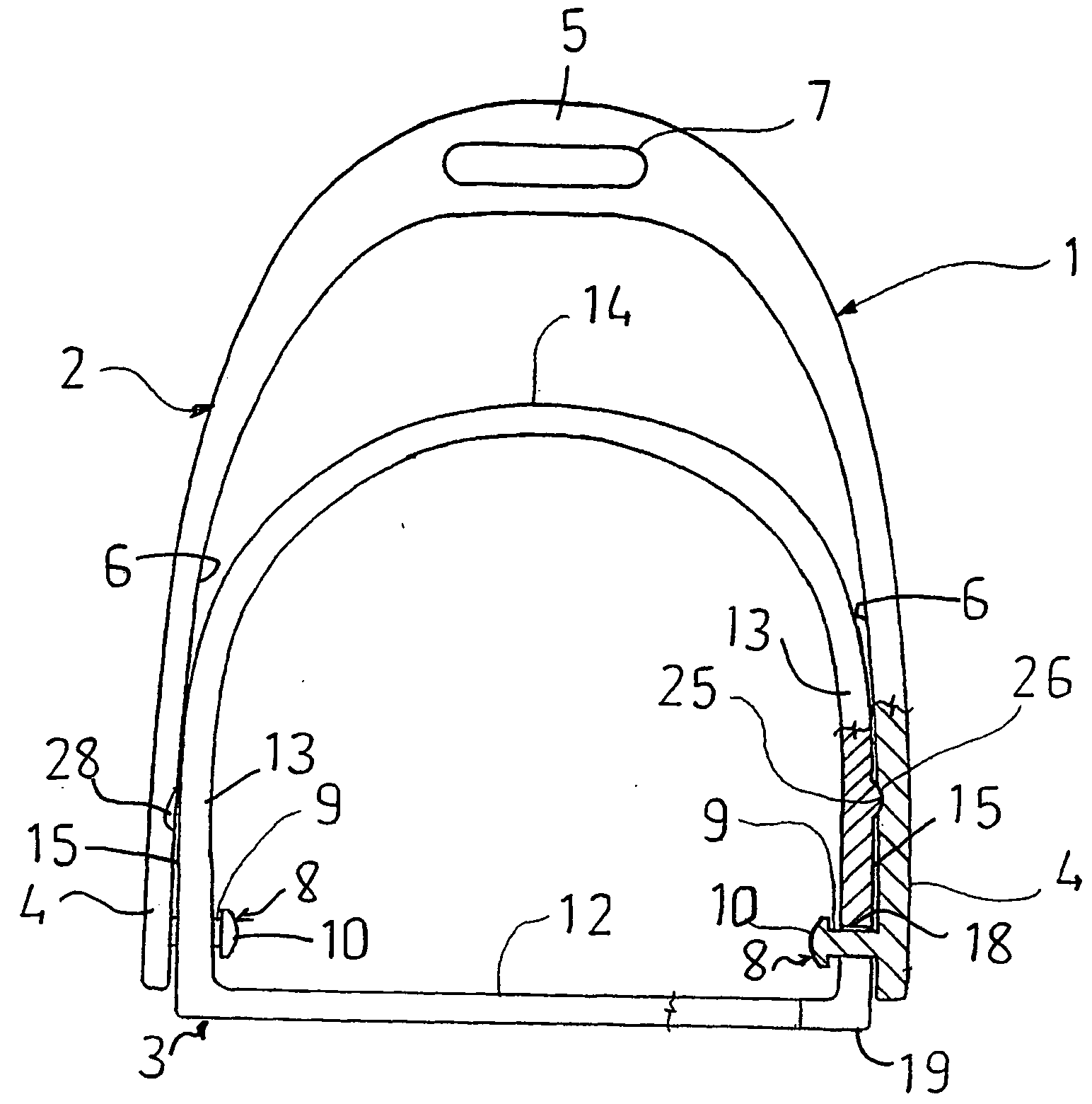
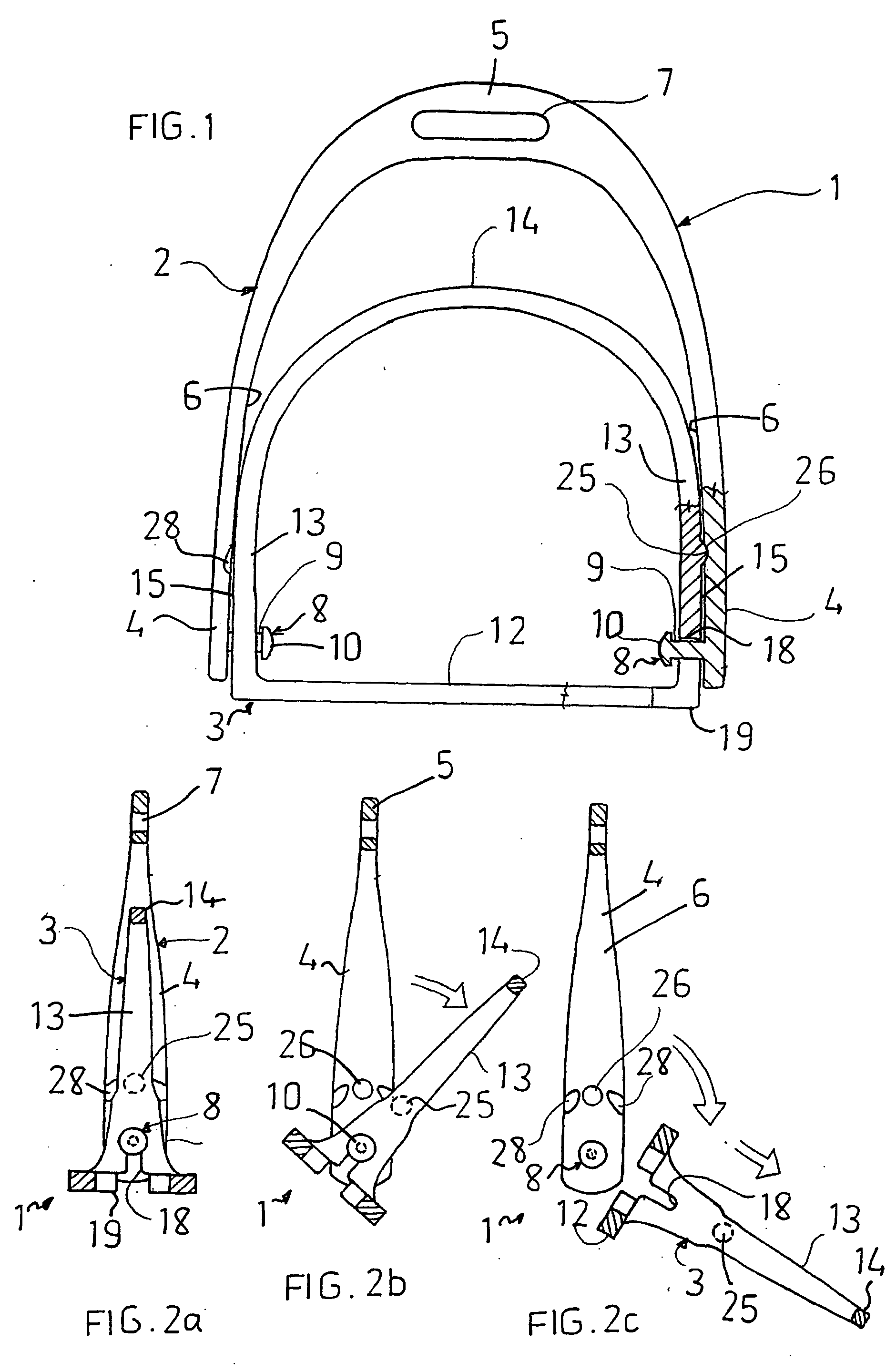
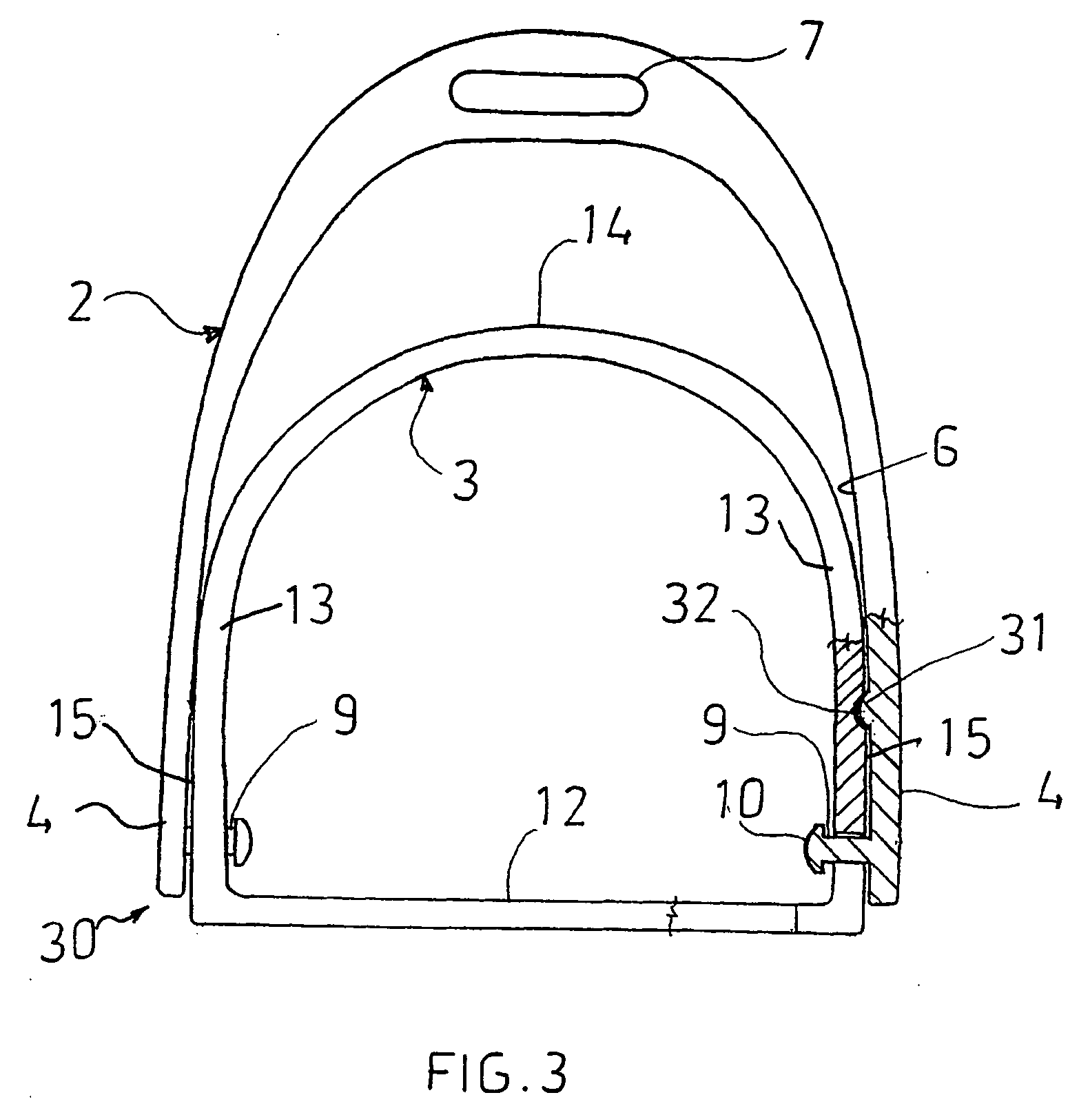
[0042] With reference to FIGS. 1 and 2a to 2c, there is shown a safety stirrup 1 comprising a mounting member 2, a foot support 3 pivotally mounted to the mounting member 2, and co-operating engagement means 25, 26 between the foot support 3 and the mounting member 2. The stirrup 1 is made of metal or plastics material.

[0043] The mounting member 2 is U-shaped and includes a pair of arms 4 as well as an arcuate portion 5 intermediate the arms 4. Each arm 4 has an inner face 6. A slot 7 for a stirrup strap extends within the intermediate arcuate portion 5. A pin 8, having a cylindrical shaft 9 and an enlarged head 10 at the end thereof, extends from the inner face 6 of each arm 4.

[0044] The foot support 3 has a tread 12 and extensions 13 that extend upwardly from opposing ends of the tread 12. The extensions 13 meet to form a loop 14 above the tread 12. The extensions 13 are adjacent opposing ends of the tread 12...


PUM


Abstract

The present invention provides a safety stirrup (1) comprising an inverted U-shaped mounting member (2) having an adaptation (7) in an arcuate portion (5) thereof for attachment of a stirrup strap thereto, a foot support (3) pivotally mounted between arms (4) of the mounting member (2) when the stirrup (1) is in normal use, wherein the foot support (3) comprises a tread (12) having an extension (13) projecting upwardly from each end of the tread (12), the distal ends of which extensions (13) join to form a loop (14). The stirrup (1) also has co-operating engagement means (25, 26) between the foot support (3) and the mounting member (2) to retain the loop (14) in a plane generally coincident with a central plane of the mounting member (2) when the stirrup (1) is in normal use. Rotation of the foot support (2) from the normal in use position disconnects the pivotal mountings and allows separation of the foot support (3) from the mounting member (2).

Description

TECHNICAL FIELD [0001] This application is a continuation-in-part of U.S. application Ser. No. 10 / 478,291 filed Apr. 9, 2002.[0002] The invention relates to horse riding stirrups and is particularly concerned with safety stirrups, which prevent the rider's foot from being caught in the stirrup in the event of the inadvertent dismounting of the rider such as being thrown from the horse. BACKGROUND ART [0003] Known types of stirrups generally include a D-shaped metal structure with a slot located in the centre of an intermediate arcuate portion of the D to enable the stirrup to be attached to a stirrup strap. In use, the rider's foot is inserted into the stirrup such that a base portion defined by an inner surface of the upright of the D of the stirrup locates against the sole of the rider's foot and the arcuate portion of the stirrup locates against the top of the rider's foot. In this way the rider's foot is held in place and is not easily dislodged from the stirrup when the gait of...

Claims


Application Information

Patent Timeline
Patent Type & Authority Applications(United States)
IPC IPC(8): B68C3/00B68C3/02
CPCB68C3/02B68C2003/0066
Inventor ZILLMER, PETER
Owner ZILLMER PETER
Learn More