
Method of bonding terminal

a terminal and terminal technology, applied in the field of terminals, can solve problems such as the reduction of the working time of bonding, and achieve the effect of preventing solder from excessively spreading

Inactive Publication Date: 2011-02-01
TOSHIBA STORAGE DEVICE CORP
View PDF4 Cites 1 Cited by
  • Summary
  • Abstract
  • Description
  • Claims
  • Application Information

AI Technical Summary

Benefits of technology

This method effectively prevents solder from spreading outside the terminal contours, avoiding short circuits and reducing bonding time by enhancing heat transfer efficiency, allowing for simultaneous bonding of multiple terminals.

Problems solved by technology

This results in a reduction in the working time of bonding.

Method used


Image

  • Method of bonding terminal
  • Method of bonding terminal
  • Method of bonding terminal

Examples


Embodiment Construction

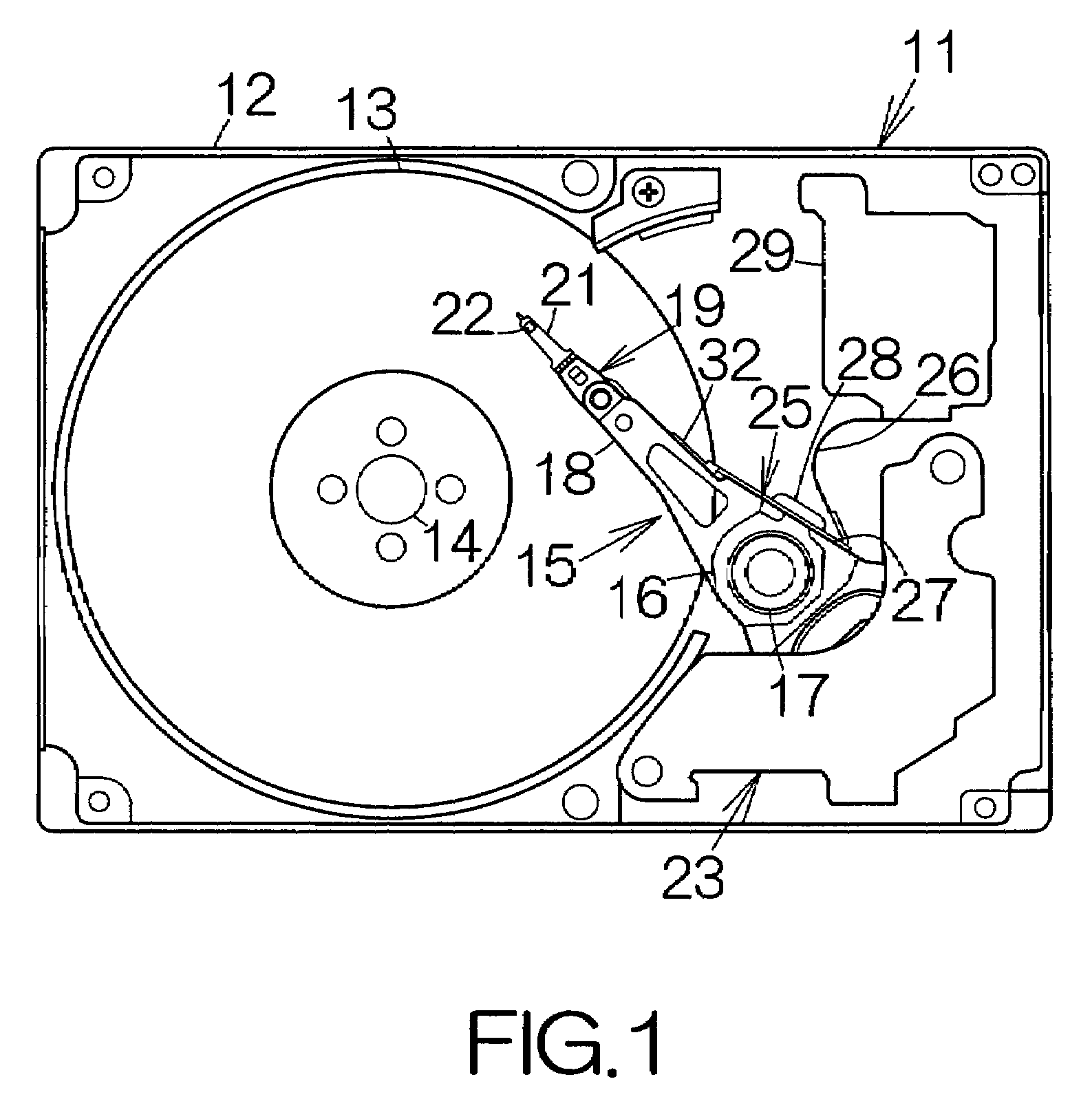
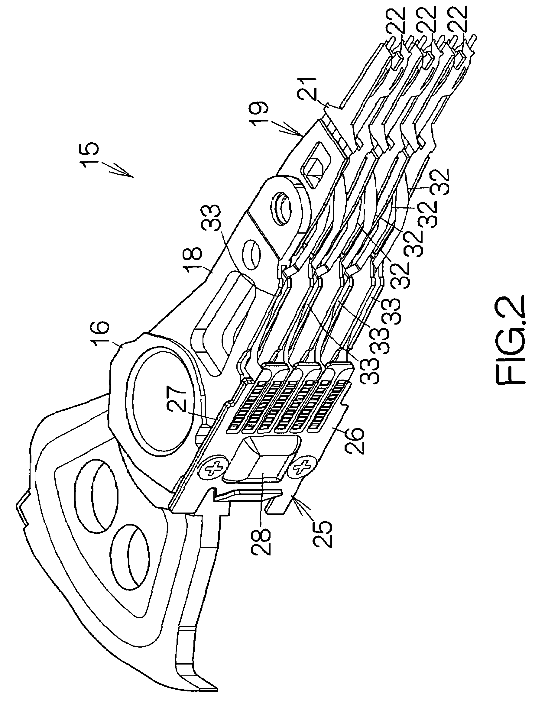
[0035]FIG. 1 schematically illustrates the inner structure of a hard disk drive, HDD, 11 as an example of a recording medium drive or storage device according to the present invention. The hard disk drive 11 includes a box-shaped enclosure body 12 defining an inner space of a flat parallelepiped, for example. The enclosure body 12 may be made of a metallic material such as aluminum, for example. Molding process may be employed to form the enclosure body 12. An enclosure cover, not shown, is coupled to the enclosure body 12. The enclosure cover closes the opening of the enclosure body 12. Pressing process may be employed to form the enclosure cover out of a plate material, for example.

[0036]At least one magnetic recording disk 13 as a recording medium is enclosed in the enclosure body 12. The magnetic recording disk or disks 13 are mounted on the driving shaft of a spindle motor 14. The spindle motor 14 drives the magnetic recording disk or disks 13 at a higher revolution speed such ...


PUM

PropertyMeasurementUnit
melting pointaaaaaaaaaa
length L1aaaaaaaaaa
length L2aaaaaaaaaa

Abstract

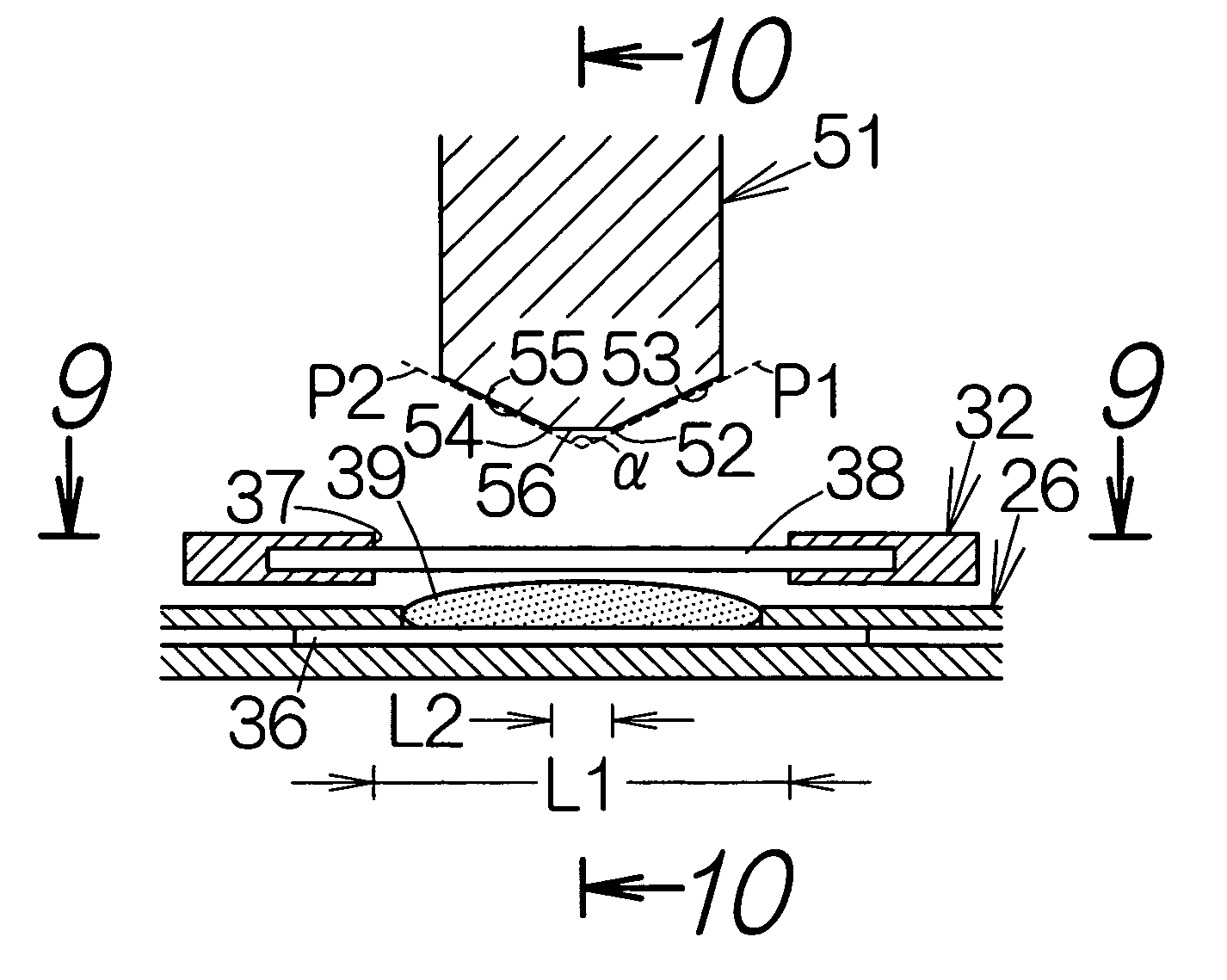
The tip end of the bonding tip is defined between first and second edges. A first inclined surface gets remoter from a first terminal at a position remoter from the first edge. The second inclined surface likewise gets remoter from the first terminal at a position remoter from the second edge. The solder is contoured by first and second contours on the first terminal. The second terminal is located on the solder between the first and second contours. The tip end of the bonding tip is urged against the second terminal. Heat is transferred from the bonding tip to the solder. The melted solder spreads into gaps between the second terminal and the first and second inclined surfaces. The solder is thus prevented from spreading outside the contour of the first terminal. This results in a reliable avoidance of a short circuit between the adjacent first terminals.

Description

BACKGROUND OF THE INVENTION[0001]1. Field of the Invention[0002]The present invention relates to a method of bonding a second terminal to a first terminal, comprising urging a second terminal against a solder located on a first terminal.[0003]2. Description of the Prior Art[0004]A carriage is incorporated in a hard disk drive, HDD. A first flexible printed circuit board is fixed to the side surface of the carriage. A flying head slider is fixed to the tip end of the carriage. A second flexible printed circuit board is utilized to connect the flying head slider to the first flexible printed circuit board. A sensing current and a writing current are supplied to the flying head slider from the first flexible printed circuit board through the second flexible printed circuit board.[0005]First terminals are arranged on the first flexible printed circuit board. An opening is defined in the second flexible printed circuit board. Second terminals are arranged in the opening. The individual s...

Claims


Application Information

Patent Timeline
Patent Type & Authority Patents(United States)
IPC IPC(8): H01R9/00H05K3/00
CPCG11B5/486H05K3/363G11B25/043H05K3/3494Y10T29/49149H05K2201/0394H05K2203/0195H05K2203/0278Y10T29/49126H05K2201/0382
Inventor YAMAGUCHI, HIDEKITOKAIRIN, KOUICHISUZUKI, HIROFUMIKOBAYASHI, HIROAKIMINAMI, HIROSHI
Owner TOSHIBA STORAGE DEVICE CORP
Learn More