Stepladder leg latches

a technology of latches and ladders, applied in ladders, construction, building construction, etc., can solve problems such as potential stability problems

Inactive Publication Date: 2006-06-15
VOSBEIN JENSEN FINN
View PDF19 Cites 19 Cited by
  • Summary
  • Abstract
  • Description
  • Claims
  • Application Information

AI Technical Summary

Benefits of technology

[0006] This invention improves upon the existing art by providing a latch that may be secured to one leg of a stepladder, including a hinged portion to engage with the other leg of the s

Problems solved by technology

When this happens, the back legs 108 hit the fl

Method used


Image

  • Stepladder leg latches
  • Stepladder leg latches
  • Stepladder leg latches

Examples


Embodiment Construction

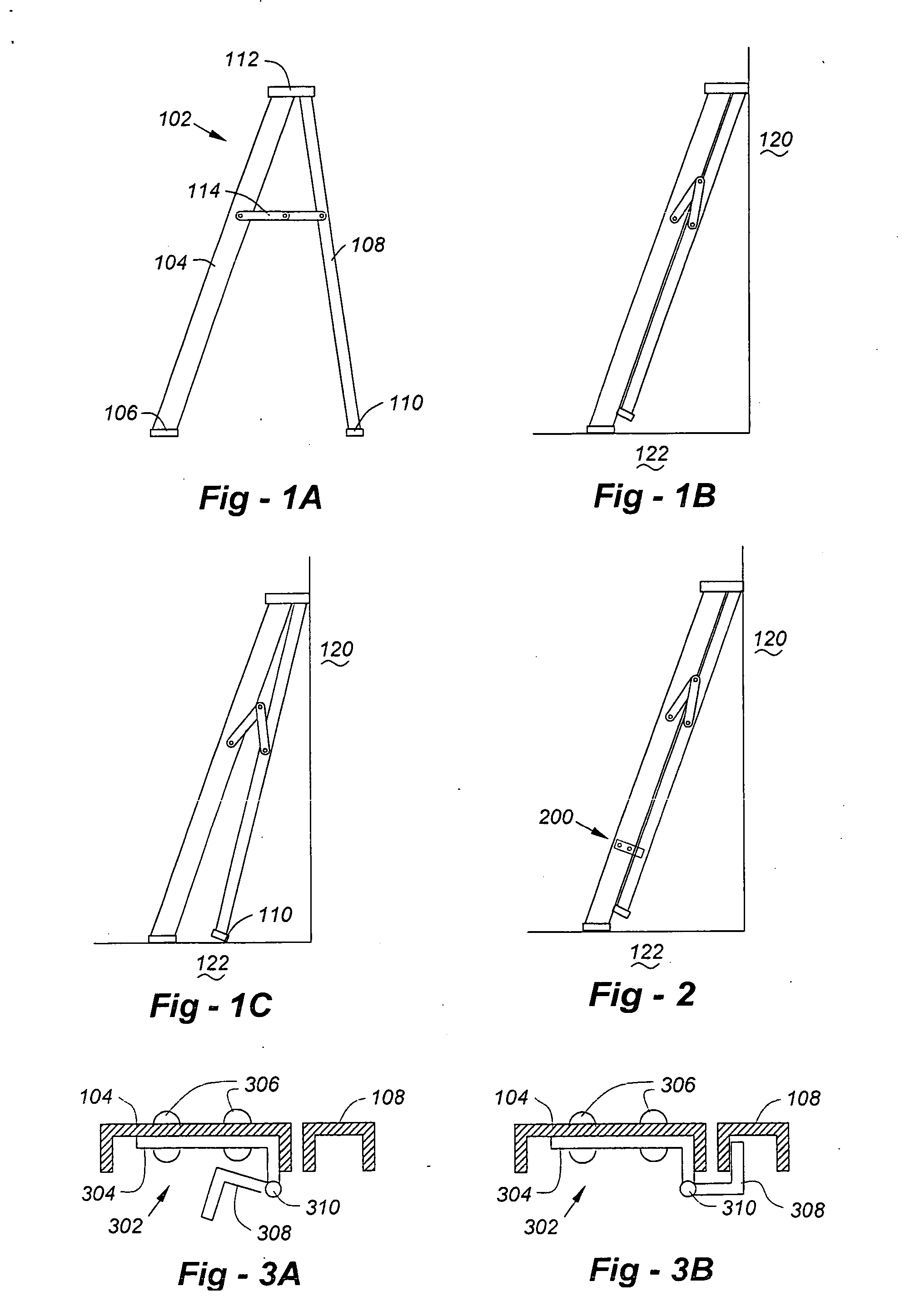
[0025] Turning now to the drawings and having discussed FIG. 1, FIG. 2 shows, from a side-view perspective, a stepladder leaned up against a wall, with a latch 200 according to the invention used to hold the two legs of the ladder together, as will be described in greater detail with respect to the preferred and alternative embodiments. Although two latches according to the invention may be provided, one on either side of the ladder, only a single latch is actually required. In terms of construction, the latches according to this invention are preferably made from steel or other metal, such as galvanized plate steel having a thickness in the range of one-sixteenth to one-quarter of an inch. The device is preferably mounted between steps, usually at a height of 12″ to 36″ from the bottom of the front legs, depending upon the overall height of the ladder.

[0026]FIG. 3A is a cross-sectional view of a latch 302 according to the invention in an unlatched state for use with extruded ladde...


PUM


Abstract

Latches are used to secure the legs of a stepladder during transport or while the ladder is leaned up against a wall or other surface. Embodiments for both extruded and solid-leg ladders are disclosed. A latch according to the invention includes a first latch portion mounted to one of the legs of the stepladder, and a second latch portion hingedly affixed to the first latch portion. In an unlatched state, the second portion is folded out of the way, enabling the stepladder to be used as a stepladder, and in a latched state, the second portion folded onto the other leg of the stepladder to hold the two legs together. A method according to the invention of latching the legs of a stepladder having a set of front legs with steps spanning right and left inside portions and a set of back legs also right and left inside portions, comprises the steps of: providing a latch with first and second hinged portions, fastening the first portion to the inside portion of one of the front legs between tow of the steps, and folding the second portion on onto one of the back legs so that the legs are latched together.

Description

REFERENCE TO RELATED APPLICATIONS [0001] This application claims priority from U.S. Provisional Patent Application Ser. No. 60 / 635,374, filed Dec. 10, 2004, the entire content of which is incorporated herein by reference.FIELD OF THE INVENTION [0002] This invention relates generally to ladder accessories, and, in particular, to a device for holding the legs of a stepladder together so that it may be more easily leaned up against a wall or other surface. BACKGROUND OF THE INVENTION [0003] A typical stepladder, illustrated in FIG. 1A at 102, includes front legs 104 terminating in floor pad 106, back legs 108 terminating in floor pads 110, a top platform 112 and a stabilizing hinge 114. The back legs 108 are generally shorter than the front legs 104. On occasion, users of stepladders desire to lean the ladder up against a wall 120, as shown in FIG. 1B. This does not create a problem if the legs remain together; however, even with hinges 114, the legs spread apart. When this happens, th...

Claims


Application Information

Patent Timeline
IPC IPC(8): E06C1/00
CPCE06C1/20E06C1/39E06C7/50
Inventor VOSBEIN-JENSEN, FINN
Owner VOSBEIN JENSEN FINN
Why Eureka
Try Eureka