Switched capacitor house of cards power amplifier

a power amplifier and capacitor technology, applied in gated amplifiers, process and machine control, instruments, etc., can solve the problems of reducing the breakdown capability of devices, occupying significant real estate for transceivers, and tax battery li

Active Publication Date: 2019-06-25
RGT UNIV OF CALIFORNIA
View PDF11 Cites 4 Cited by
  • Summary
  • Abstract
  • Description
  • Claims
  • Application Information

AI Technical Summary

Problems solved by technology

Typical transceivers utilize lossy transformers, which tax battery life.
The typical transceivers also occupy significant real estate, because a power amplifier is built in a separate chip using expensive non-CMOS (complementary metal-oxide-semiconductor) technology (e.g., heterojunction bipolar transistors (HBT)) and then assembled into the system via difficult and expensive heterogeneous integration techniques.
Scaling produces thinner oxide devices, which saves chip real estate but reduces the voltage blocking breakdown capability of the devices.
The capability of such devices to produce high voltage and to pump power into the widely used 50Ω antenna weakens because of the lower voltage blocking capability.
This creates difficulties for the monolithic integration of the PA power stage into a digital CMOS chip, and negatively impacts the cost and size reductions.
The ability to leverage the huge processing capabilities of CMOS DSPs (digital signal processors) is also compromised.
Conventional circuits and methods make it difficult to efficiently generate high levels of RF power in scaled CMOS largely due to the inherently low voltage ratings of core thin-oxide transistors.
These AC-AC losses, combined with the DC-AC losses of the power amplifiers (PAs) themselves, and the DC-DC losses of the battery-connected power converters, result in limited total transmitter efficiencies.
Even modern digital PA techniques such as RF-DACs, digital Doherty, and digital out-phasing, which have been proposed to leverage the excellent switch performance of scaled transistors and offer reconfigurable operation, still require battery-connected DC-DC converters and RF transformers / power combiners, both of which result in cascaded losses.
Unfortunately, such approaches require either off-chip or large on-chip inductors for high efficiency.

Method used


Image

  • Switched capacitor house of cards power amplifier
  • Switched capacitor house of cards power amplifier
  • Switched capacitor house of cards power amplifier

Examples


Embodiment Construction

[0027]Preferred embodiments of the invention provide high-voltage RF power generation via a DC-RF power amplifier inverter topology that achieves implicit DC-DC conversion, solid-state impedance transformation, and high-efficiency at back-off, all in a single circuit. Preferred topologies can use, but don't require, thin oxide transistors. However, preferred topologies are independent of the type and size of transistors utilized.

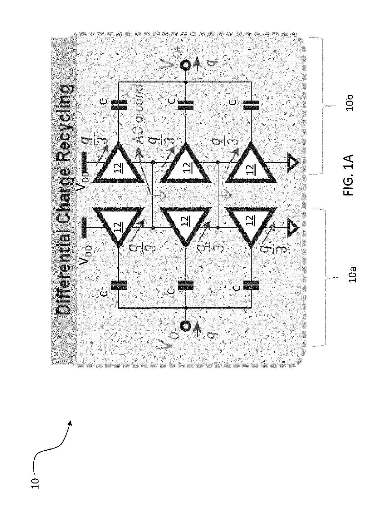
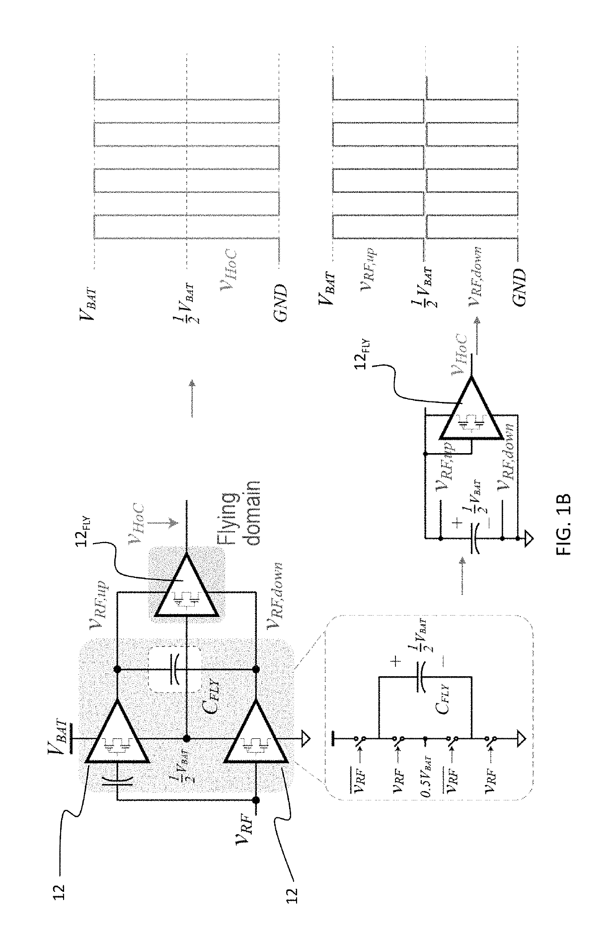
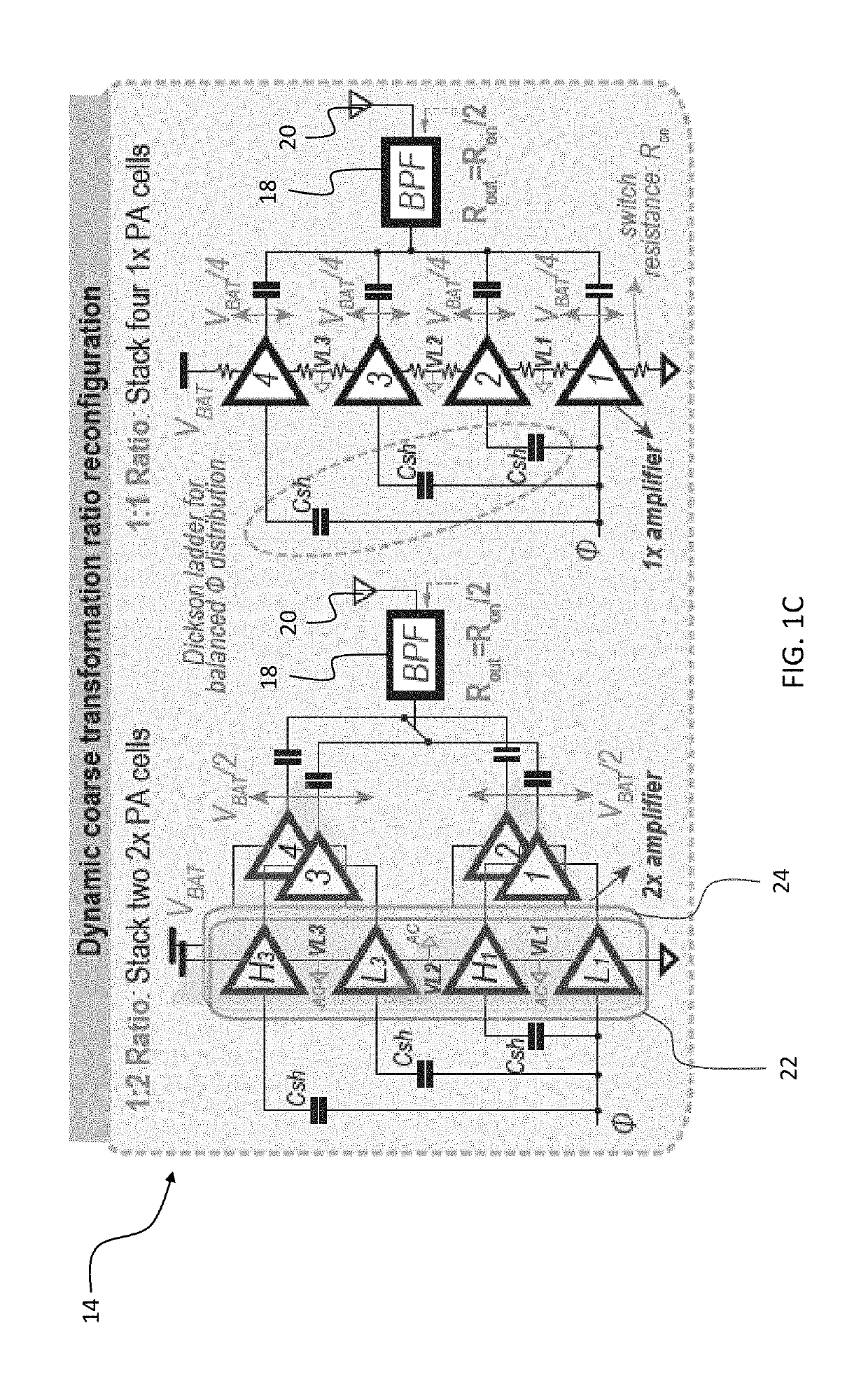
[0028]In preferred circuits, high efficiency across a wide output range is primarily achieved by 3 techniques: 1) a ˜100% efficiency implicit DC-DC conversion approach that vertically stacks PA cells (i.e., by connecting the positive supply terminal of the bottom PA cell to the negative supply terminal of the stacked PA cell) in a ladder topology; 2) flying the individual PA cells, in relation to the battery rails, in a 2-phase recursive house-of-cards (RHoC) switched-capacitor network (i.e., where a stack of N PA cells connect to a stack of N−1 PA cells in ...


PUM


Abstract

A circuit topology including stacked power amplifiers (e.g., class D PA cells) in a ladder arranged in a house-of-cards topology such that the number of stacked-domains follows a decaying triangular series N, N−1, N−2, . . . , N−i from a fixed ladder to an ith ladder to provide a 1:(i+1) voltage conversion ratio, each stacked domain outputs its power via a flying domain power amplifier cell, and each ladder balances stacked domains of a prior ladder and combines power from all prior ladders.

Description

PRIORITY CLAIM AND REFERENCE TO RELATED APPLICATION[0001]The application claims priority under 35 U.S.C. § 119 and all applicable statutes and treaties from prior U.S. provisional application Ser. No. 62 / 384,912, which was filed Sep. 8, 2016.STATEMENT OF GOVERNMENT INTEREST[0002]This invention was made with government support under Grant No. D15AP00091 awarded by Defense Advanced Research Projects Agency (DARPA). The government has certain rights in the invention.FIELD[0003]A field of the invention is power conversion, including power efficient DC power into an AC, as well as DC-DC, AC-DC-AC, and AC-DC conversion. Another field of the invention is transceiver devices. Example applications of circuits and methods of the invention include RF power amplifiers (PA), 20 kHz audio amplifiers, and 50-60 Hz power inverters. The invention can be applied advantageously in portable electronics. Power amplifiers of the invention can provide longer battery operational-time and smaller form-facto...

Claims


Application Information

Patent Timeline
Patent Type & Authority Patents(United States)
IPC IPC(8): H03F1/07H03F3/217H02M3/158H03F3/21H03F3/24H03F3/72
CPCH03F3/2171H02M3/1582H03F3/211H03F3/245H03F3/72H03F3/2173H03F2200/451
Inventor SALEM, LOAI GALAL BAHGATBUCKWALTER, JAMES F.MERCIER, PATRICK P.
Owner RGT UNIV OF CALIFORNIA
Why Eureka
Try Eureka