Pneumatic tire

a technology of pneumatic tires and cylinders, applied in the field of pneumatic tires, can solve the problems of unfavorable traction and traction of tires, and generate even wear near the acute corner portion, and achieve the effects of improving dry grip performance, large groove volume, and improving wear resistance performan

Inactive Publication Date: 2006-06-22
SUMITOMO RUBBER IND LTD
View PDF7 Cites 22 Cited by
  • Summary
  • Abstract
  • Description
  • Claims
  • Application Information

AI Technical Summary

Benefits of technology

[0031] The pneumatic tire in accordance with the present invention is structure as mentioned above. Accordingly, in an acute corner portion between the circumferential groove and the oblique groove in the land portion surrounded by the circumferential groove and the inclined groove, a rigidity is increased by the gentle decline wall of the circumferential groove in which the inclined surface width becomes large. Accordingly, it is possible to improve the dry grip performance, the wear resistance performance and the like. Further, the steel decline wall of the circumferential groove secures a large groove volume and maintains an improved drainage performance.

Problems solved by technology

Further, there is a defect that an uneven wear tends to be generated near the acute corner portion (c1).

Method used


Image

  • Pneumatic tire
  • Pneumatic tire
  • Pneumatic tire

Examples


examples

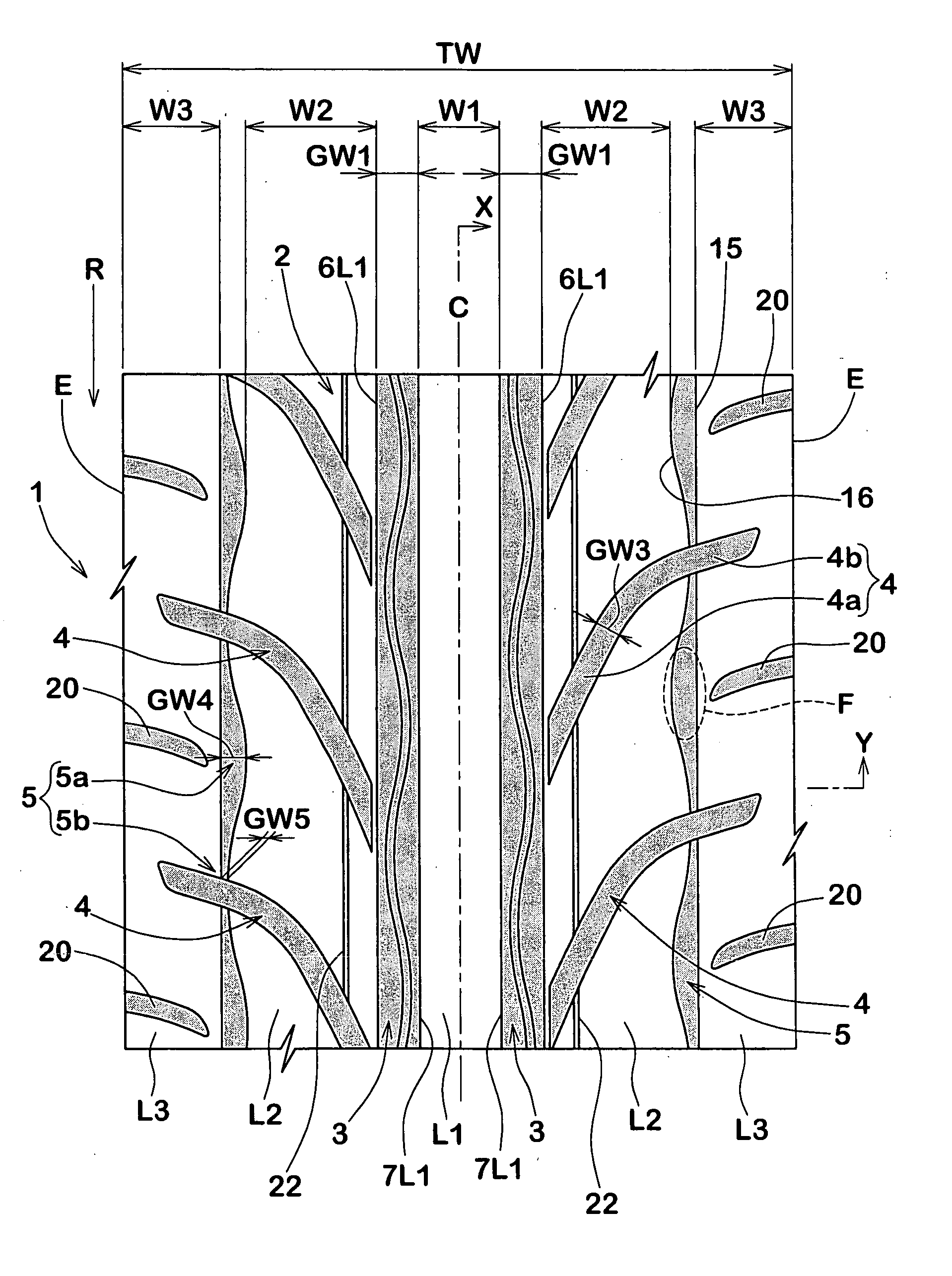
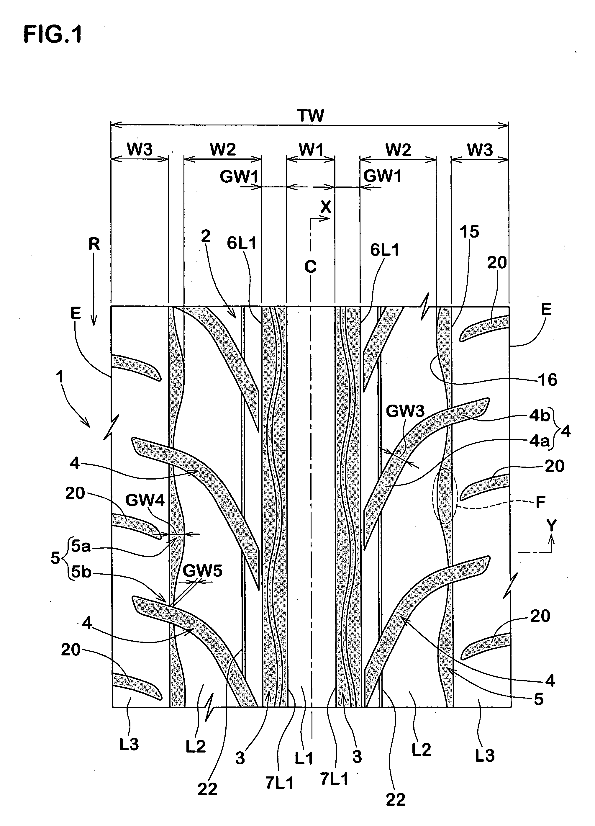
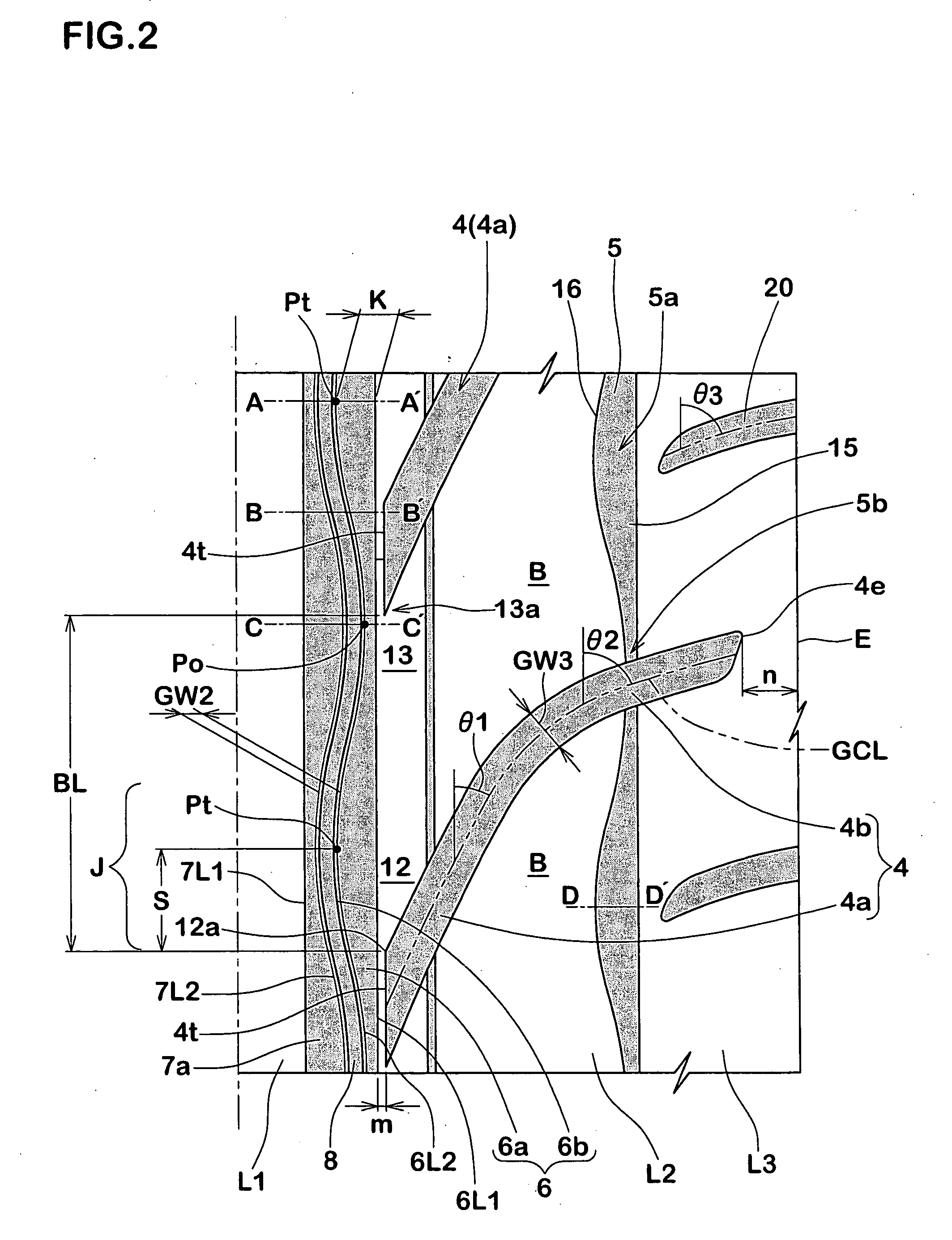
[0088] In order to confirm the effect of the present invention, a radial tire for a passenger car having a tire size of 235 / 45R17 is manufactured by way of trial, and a dry grip performance, a drainage performance and a biased wear resistance performance of each of the trial tires are tested. In each of the tires, a tread ground width TW is unified to 220 mm, a tread pattern is set in accordance with the specification in Table 1, and a performance difference is compared. In a Comparative Example 1, the inner end of the gentle decline wall of the circumferential groove extends linearly in the tire circumferential direction. In a Comparative Example 2, the inner end of the gentle decline wall of the circumferential wall extends in a wavy shape in the tire circumferential direction. However, the position of the innermost point of the inner end exists in the obtuse corner side of the land portion. Further, in a Comparative Example 3, the steel decline wall is not included in the circumf...


PUM


Abstract

A pneumatic tire is provided with a pair of circumferential grooves (3) arranged in both sides of a tire equator (C), and a plurality of oblique grooves (4) having a steep decline portion (4a) extending to an outer side in a tire axial direction at an angle (q1) between 15 and 45 degree with respect to a tire circumferential direction from a position near the circumferential groove (3), in a tread surface (2). A land portion (B) surrounded by the circumferential groove (3) and the steep decline portion (4a) has an acute corner portion (12) and an obtuse corner portion (13), each being formed between the circumferential groove (3) and the steep decline portion (4a). An outer groove wall surface (6) of the circumferential groove (3) includes a gentle decline wall (6a) in the tread surface side, and a steep decline wall (6b) in the groove bottom side.

Description

BACKGROUND OF THE INVENTION [0001] 1. Field of the Invention [0002] The present invention relates to a pneumatic tire which has, on balance, an improved drainage performance, dry grip performance and wear resistance performance. [0003] 2. Description of the Related Art [0004] As the pneumatic tire in which the dry grip performance and the drainage performance are improved, for example, there has been known a tire described in Japanese Unexamined Patent Publication No. 2004-210189. This pneumatic tire has a tread face with a tread pattern which is provided with a circumferential groove (g1) extending in a tire circumferential direction, and a plurality of oblique grooves (g2) extending from the circumferential groove (g1) toward tread edges at a comparatively small angle with respect to the tire circumferential direction as shown in FIG. 11. [0005] In the tread pattern mentioned above, a land portion (r) is formed in a region adjacent to the circumferential groove (g1) and between th...

Claims


Application Information

Patent Timeline
Patent Type & Authority Applications(United States)
IPC IPC(8): B60C11/13
CPCB60C11/0302B60C11/0309B60C11/1323B60C2011/0388B60C11/1315B60C2011/0374
Inventor MURATA, TAKEHIKO
Owner SUMITOMO RUBBER IND LTD
Why Eureka
Try Eureka