
Device of forming tire reinforcing layer

a technology of reinforcing layer and tire, which is applied in the field of reinforcing layer forming device of tire, can solve the problems of large space and high cost of manufacturing facilities, and achieve the effect of reducing the resistance at the time of affixing

Inactive Publication Date: 2006-06-22
BRIDGESTONE CORP
View PDF3 Cites 10 Cited by
  • Summary
  • Abstract
  • Description
  • Claims
  • Application Information

AI Technical Summary

Benefits of technology

[0022] Accordingly, the tire reinforcing layer forming device of the present invention has the effect that it can form, by a single device, plural reinforcing layers whose cord directions intersect one another.
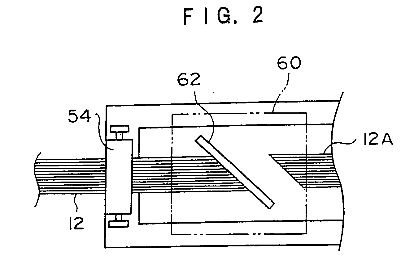
[0025] Because the cut reinforcing material pieces are affixed at an incline with respect to the axial direction of the drum, by inclining the reinforcing material exit of the first conveying path and the reinforcing material exit of the second conveying path with respect to the drum axial direction, the inclinations of the reinforcing material pieces can be set accurately, and further, it suffices to not twist the reinforcing material pieces at the time of affixing them to the drum, and therefore, the resistance at the time of affixing is decreased.

Problems solved by technology

Thus, there are the problems that the manufacturing facilities are expensive and require a wide space for placement.

Method used


Image

  • Device of forming tire reinforcing layer
  • Device of forming tire reinforcing layer
  • Device of forming tire reinforcing layer

Examples


Embodiment Construction

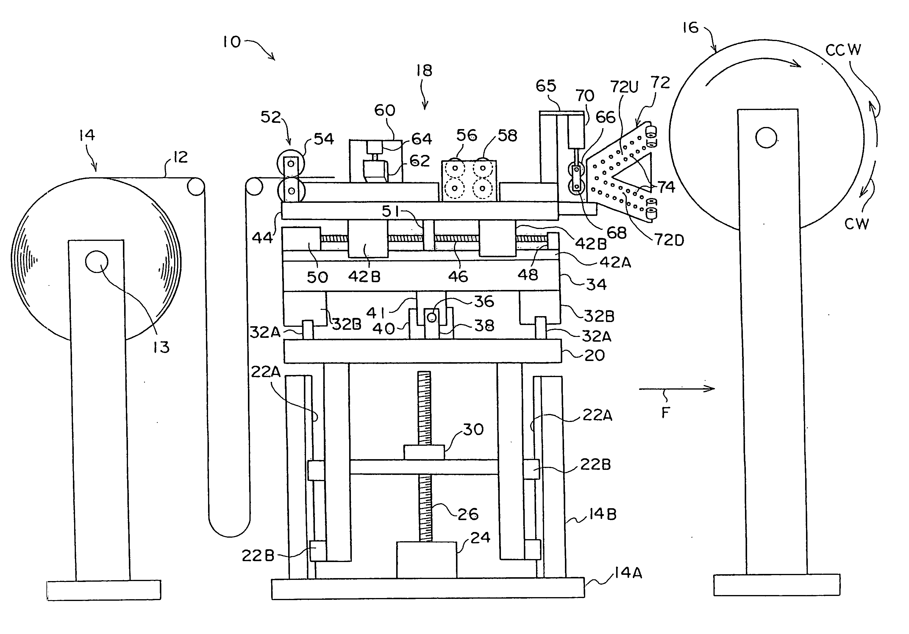
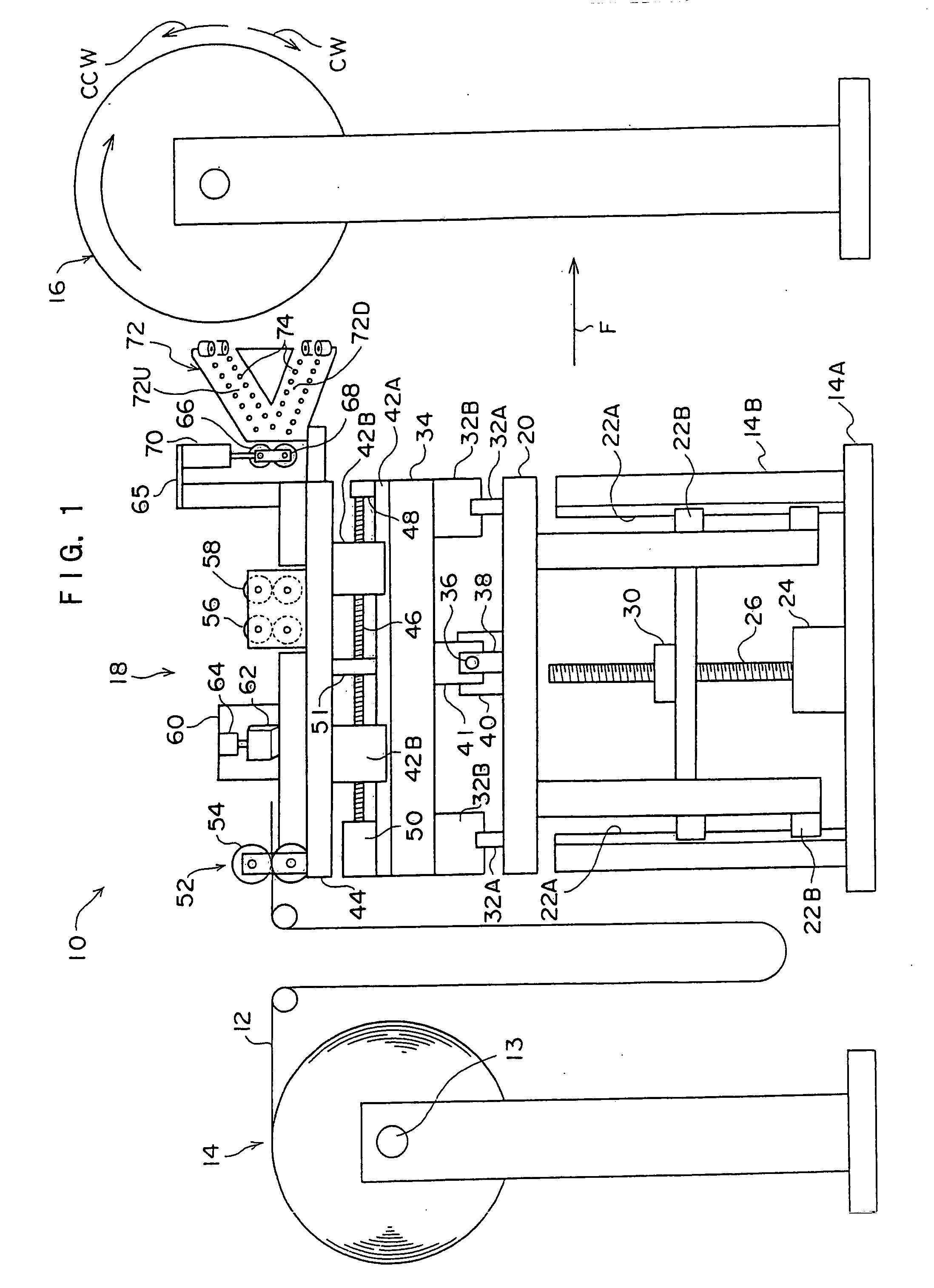
[0040] Next, a tire reinforcing layer forming device 10 relating to an embodiment of the present invention will be described in accordance with FIG. 1 through FIG. 4.

[0041] As shown in FIG. 1, the tire reinforcing layer forming device 10 of the present embodiment has a reinforcing material supplying device 14 which removably supports a shaft 13 around which is wound a strip-shaped reinforcing material 12, a drum 16 to which the reinforcing material 12 is affixed, and an affixing device 18 which affixes the reinforcing material 12 to the drum 16.

[0042] The affixing device 18 has a base 18A which is set on a floor surface. A pair of supporting columns 18B, which extend along the vertical direction, stand erect at the top surface of the base 18A.

[0043] An up / down sliding member 20 is disposed between the pair of supporting columns 18B.

[0044] Slide rails 22A are mounted to the side surfaces of the supporting columns 18B. Slide units (e.g., linear motion bearings or the like) 22B, wh...


PUM

PropertyMeasurementUnit
lengthaaaaaaaaaa
timeaaaaaaaaaa
resistanceaaaaaaaaaa

Abstract

An object is to provide a tire reinforcing layer forming device which can form, by a single device, plural reinforcing layers whose cord directions intersect one another. A reinforcing material piece 12A, which is distributed to an upper conveying path 72U, is affixed from a left end side of a drum 16 toward a right side, while the drum 16 is rotated in a direction of arrow CW. In this way, the reinforcing material piece 12A, which is affixed to an outer peripheral surface of the drum 16, falls to the right, i.e., rises to the left. Thereafter, similarly, the reinforcing material pieces 12A are successively affixed without gaps, and a first reinforcing layer is formed. Next, the reinforcing material piece 12A, which is distributed to a lower conveying path 72D, is affixed from the left end side of the drum 16 toward the right side, while the drum 16 is rotated in an opposite direction. In this way, the reinforcing material piece 12A, which is affixed to an outer peripheral surface of the first reinforcing layer, rises to the right. Thereafter, similarly, the reinforcing material pieces 12A are successively affixed without gaps, and a second reinforcing layer is formed.

Description

TECHNICAL FIELD [0001] The present invention relates to a tire reinforcing layer forming device which is for forming tire reinforcing layers on an outer peripheral surface of a drum. BACKGROUND TECHNOLOGY [0002] As a tire reinforcing layer forming device which forms reinforcing layers of a pneumatic tire, there is, for example, the tire reinforcing layer forming device described in Japanese Patent Application Laid-Open (JP-A) No. 2000-301628. [0003] In this tire reinforcing layer forming device, accompanying the rotational motion of a core, a cut reinforcing material (belt) is fed from one end side onto the peripheral surface of the core, and the reinforcing material is gradually pressed onto the core peripheral surface along the entire length, so as to be press-joined thereto. [0004] However, in this tire reinforcing layer forming device, when forming a so-called intersecting belt which is formed from two belt layers whose cord directions intersect one another, there is the need, w...

Claims


Application Information

Patent Timeline
Patent Type & Authority Applications(United States)
IPC IPC(8): B29D30/70B29D30/30
CPCB29D30/1657B29D30/3057B29D30/70B29D2030/3085B29D2030/3092
Inventor MIZOTA, YASUO
Owner BRIDGESTONE CORP
Learn More