Solid-state imaging device and method for driving the same

a technology of solid-state imaging and driving mode, which is applied in the scanning details of television systems, picture signal generators, and the scanning of television systems. it can solve the problems of low flexibility of operation and degradation of processing image quality

Inactive Publication Date: 2006-06-22
SONY CORP
View PDF10 Cites 27 Cited by
  • Summary
  • Abstract
  • Description
  • Claims
  • Application Information

AI Technical Summary

Benefits of technology

[0010] According to a further embodiment of the present invention, provided is a driving method for a solid-state imaging device having a pixel array in which a plurality of pixel cells, each of which includes a plurality of photoelectric conversion elements, is arranged, and a controller for controlling an exposure times on the plurality of photoelectric conversion elements in the pixel array. The method includes the step of causing the controller to control the exposure times using a ratio determined according to the arrangement of the plurality of photoelectric conversion elements when the addition operation is performed on the plurality of signals output from the plurality of photoelectric conversion elements in the pixel array in a predetermined combination.

Problems solved by technology

However, this known method has a disadvantage of low flexibility in operation, since it performs simple addition and averaging operations during reading.
This results in an image inconsistent with an expected low-resolution image in the Bayer array, which causes degradation of the quality in the processed image.

Method used


Image

  • Solid-state imaging device and method for driving the same
  • Solid-state imaging device and method for driving the same
  • Solid-state imaging device and method for driving the same

Examples


first embodiment

[0035]FIGS. 3A and 3B are conceptual diagrams illustrating a technique in a known art and a first embodiment of the present invention, respectively. Virtual pixel centers, which are obtained by mixing two pixels of an identical color when pixels corresponding to G (green) and B (blue) are alternatively arranged in a column, are illustrated in these figures. FIG. 3A illustrates an addition operation according to the known art. Since two pixel signals, each from a single pixel of the identical color, are simply added and averaged, pitches between the centers of each pair of the adjacent virtual pixels G′ and B′ after addition are not equal.

[0036] In contrast, FIG. 3B illustrates an addition operation according to the first embodiment of the present invention. The pitches between the centers of each pair of the adjacent virtuals G′ and B′ after addition can be equalized by setting a specific value of addition ratio between the input signals in an analog signal processing. In other wor...

second embodiment

[0043] In the first embodiment, an addition operation is performed in the sampling portion in a CDS circuit. However, for an image sensor configured to have a FD portion shared between pixel cells, a charge-addition operation in the FD portion is more advantageous for high sensitivity and operational speed. In this case, addition and averaging operations for signal processing similar to those described in the first embodiment can be achieved, by adjusting an exposure time on each pixel intended for an addition operation, as shown in FIG. 7.

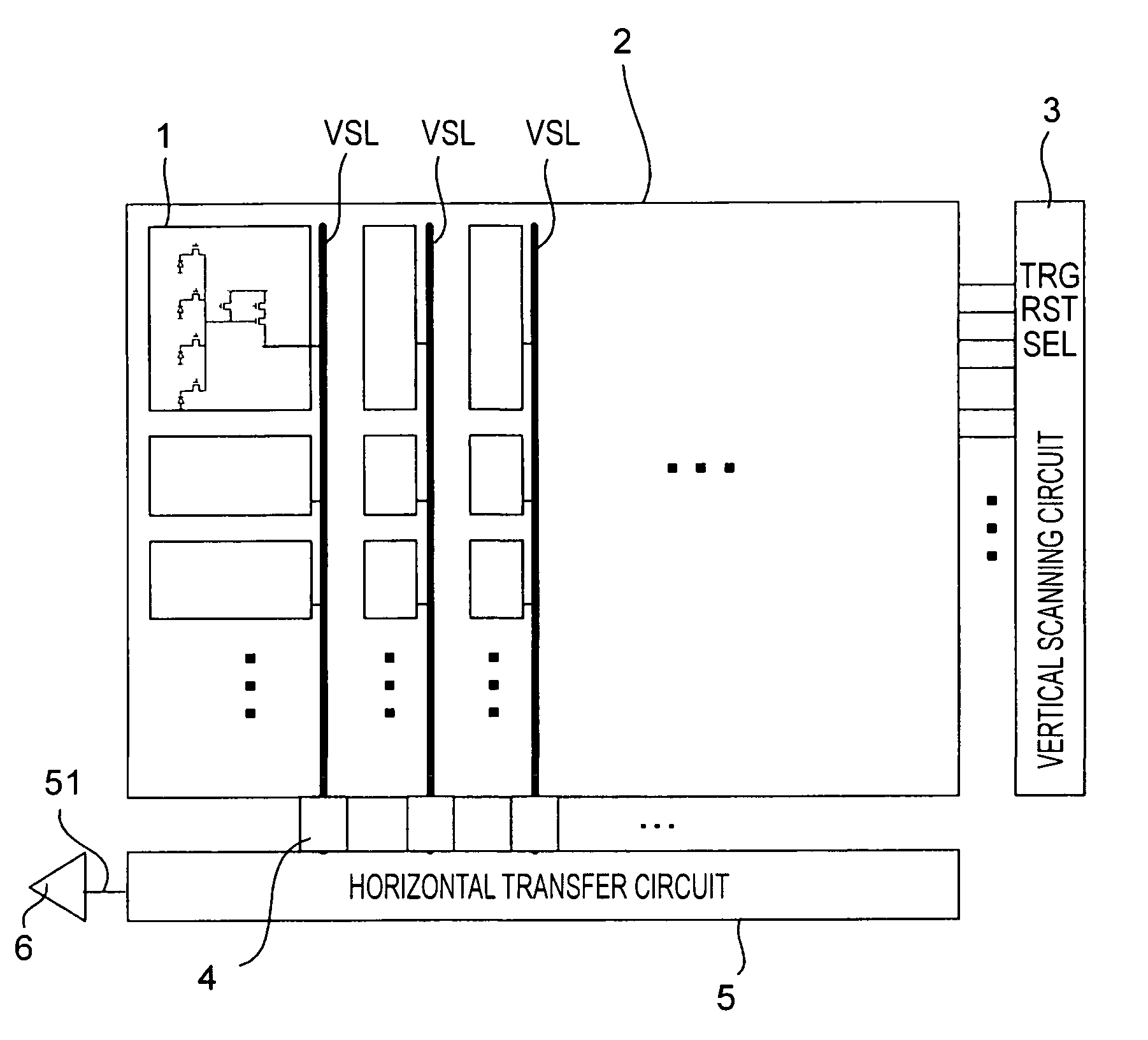
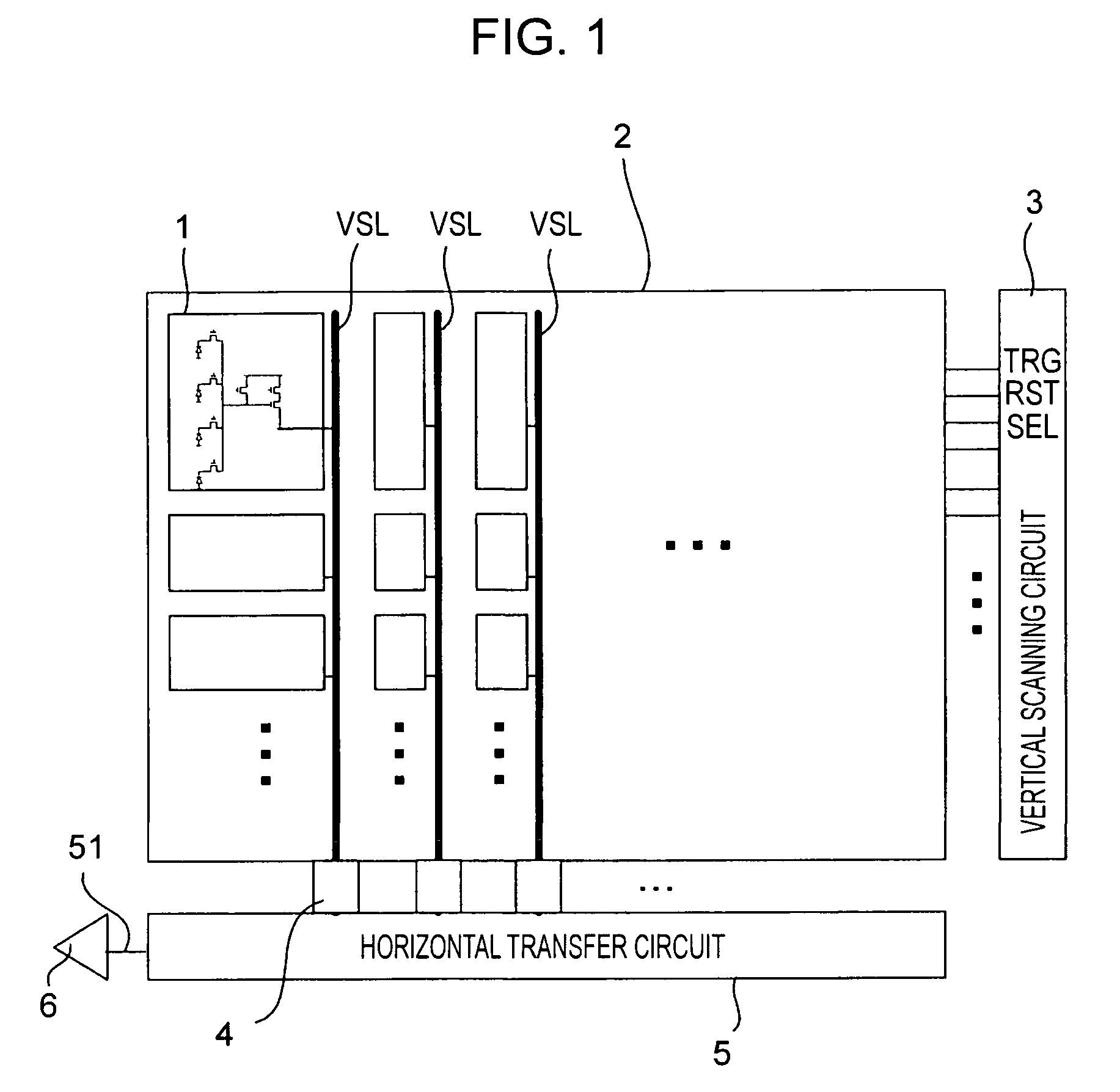
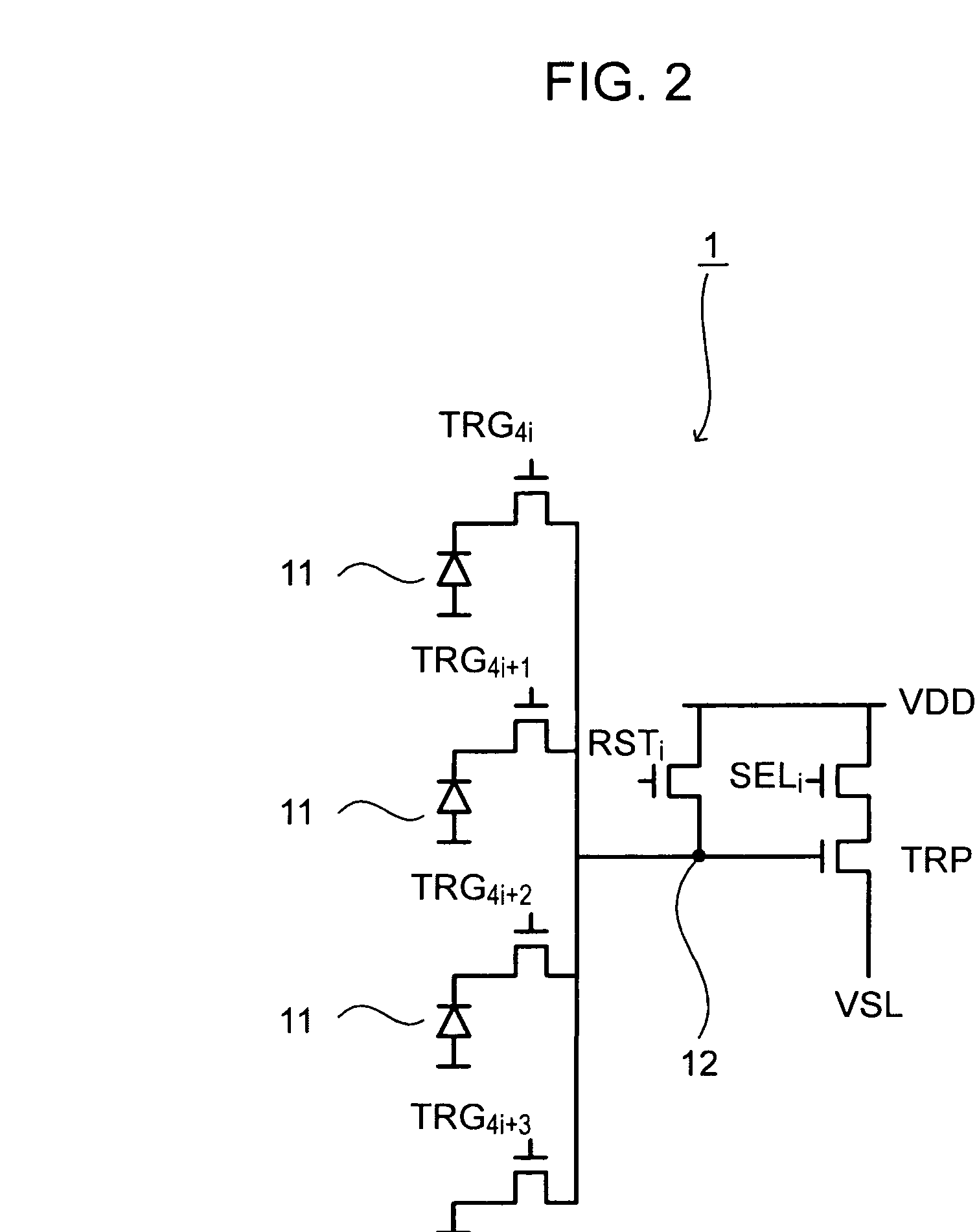
[0044] Specifically, a vertical scanning circuit 3 performs a control operation, so that the time interval between ON periods (exposure time) of a transfer transistor TRG_a of a first pixel intended for an addition operation may be set to be the normal exposure time, and the time interval between ON periods of a transistor TRG_b of a second pixel intended for the addition operation may be set to be one-third shorter than that of TRG_a. This yield...

third embodiment

[0046] Embodiments of the present invention may also be applicable to other signal readout configurations than the CDS circuit. For example, a signal processing technique can likewise be achieved even when a column circuit having an analog-to-digital converter (ADC) is provided for each column. For a comparison circuit in the ADC, differential circuits whose sizes i.e., amplification factors, are different from each other, e.g., Standard Size and ⅓ Size, may be connected in parallel as shown in FIG. 8. Further, it becomes possible to switch between various output resolution modes by changing the connections of a plurality of differential circuits of various sizes appropriately.


PUM


Abstract

A solid-state imaging device includes a pixel array in which a plurality of pixel cells, each of which includes a plurality of photoelectric conversion elements, is arranged, and an adder for performing an addition operation on a plurality of signals output from the photoelectric conversion elements of the pixel array in a predetermined combination of the photoelectric conversion elements, while setting between the signals to be added a ratio determined according to the arrangement of the photoelectric conversion elements.

Description

CROSS REFERENCES TO RELATED APPLICATIONS [0001] The present invention contains subject matter related to Japanese Patent Application JP 2004-367223 filed in the Japanese Patent Office on Dec. 20, 2004, the entire contents of which are incorporated herein by reference. BACKGROUND OF THE INVENTION [0002] 1. Field of the Invention [0003] The present invention relates to solid-state imaging devices for capturing images and producing image signals by means of a plurality of photoelectric conversion elements and also to driving methods for driving such imaging devices. More particularly the present invention relates to a solid-state imaging device which performs an addition operation on pixel data and then outputs the result, and to a driving method therefor. [0004] 2. Description of the Related Art [0005] In general, driving modes for an image sensor includes an all-image readout mode in which all pixels are read out for normal applications and a low-resolution readout mode in which pixe...

Claims


Application Information

Patent Timeline
Patent Type & Authority Applications(United States)
IPC IPC(8): H04N5/335H04N5/343H04N5/347H04N5/353H04N5/357H04N5/363H04N5/369H04N5/374H04N5/378H04N9/07
CPCH04N3/155H04N9/045H04N2209/045H04N25/46H04N25/533H04N23/84H04N25/71H04N25/75
Inventor KUDOH, YOSHIHARU
Owner SONY CORP
Why Eureka
Try Eureka