Vehicle-mounted equipment carrier

a technology for equipment carriers and vehicles, applied in the field of equipment carriers, can solve the problems of not being able to solve the problem very satisfactorily, the operation of arranging the straps is relatively complicated and time-consuming, and the carrier is not attractive, etc., and achieves the effect of easy and quick tightening and easy unrolling

Active Publication Date: 2006-06-29
PEDRINI
View PDF64 Cites 32 Cited by
  • Summary
  • Abstract
  • Description
  • Claims
  • Application Information

AI Technical Summary

Benefits of technology

[0004] It is an object of the present invention to provide an equipment carrier for mounting on a vehicle trunk lid or door which can be mounted on the vehicle and removed from the vehicle with extremely simple and quick operations.
[0006] It is also an object of the present invention to provide an equipment carrier for mounting on a vehicle trunk lid or door which ensures the carrier to be safely secured to the vehicle structure.
[0017] In order to mount the carrier on the vehicle, the frame of the carrier is simply placed with its lower engagement means engaged for instance on the lower edge of the rear trunk lid or door of the vehicle. One or more vehicle engaging members carried by the frame rest on the trunk lid or door and each strap member is arranged with its upper engagement means on the upper edge of the trunk lid or door. Then, each strap member can be tightened easily and quickly by the above mentioned ratchet-type tensioning means, so that the lower engagement means of the carrier frame are pressed into engagement against the lower area of the trunk lid or door, while the upper engagement means of the strap members are urged into engagement with the upper edge of the lid or door.
[0018] In a further preferred embodiment, each support carrying the strap tensioning means is provided with strap winding means for storing the strap member in a wound condition within the respective support. Thus, the carrier and the strap members integrated therein assume a particularly compact configuration when the carrier is not in use, whereas the strap members can be easily unrolled from the respective supports when the carrier must be mounted.

Problems solved by technology

Carriers of this type are encountering increasing favour among users with respect to carriers which are to be mounted on the vehicle roof, also due to the inconvenience of placing the equipment (e.g. a bicycle) on the vehicle roof, particularly with relatively tall vehicles such as Sport Utility Vehicles (SUV), vans or others.
Equipment carriers of this type which have been proposed heretofore are not able to solve this problem very satisfactorily.
The operation of arranging these straps is relatively complicated and time-consuming, and the same is true when the carrier must be removed from the vehicle.
Moreover, the addition of these straps gives rise to a not very attractive appearance of the carrier once it has been mounted on the vehicle.

Method used


Image

  • Vehicle-mounted equipment carrier
  • Vehicle-mounted equipment carrier
  • Vehicle-mounted equipment carrier

Examples


first embodiment

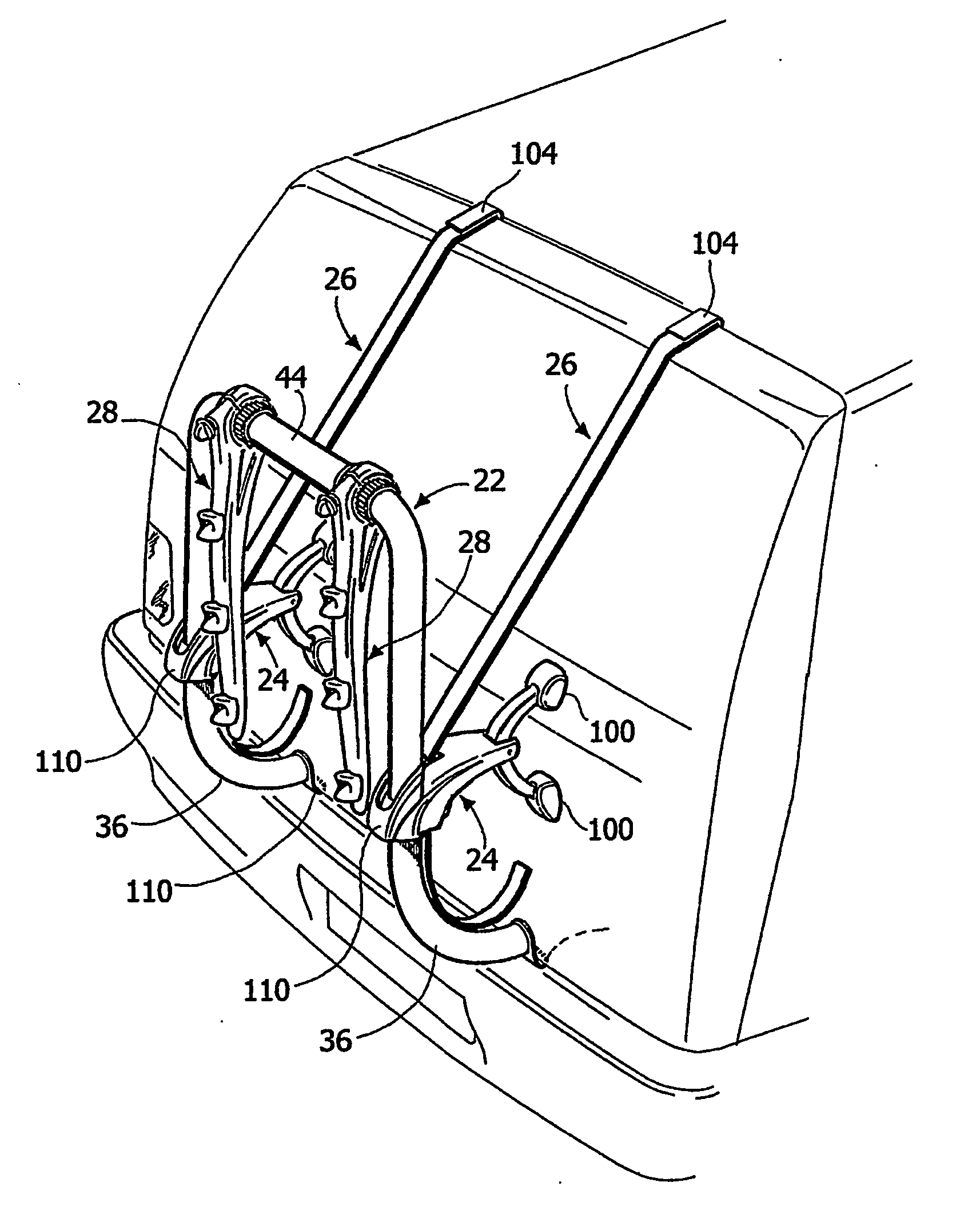
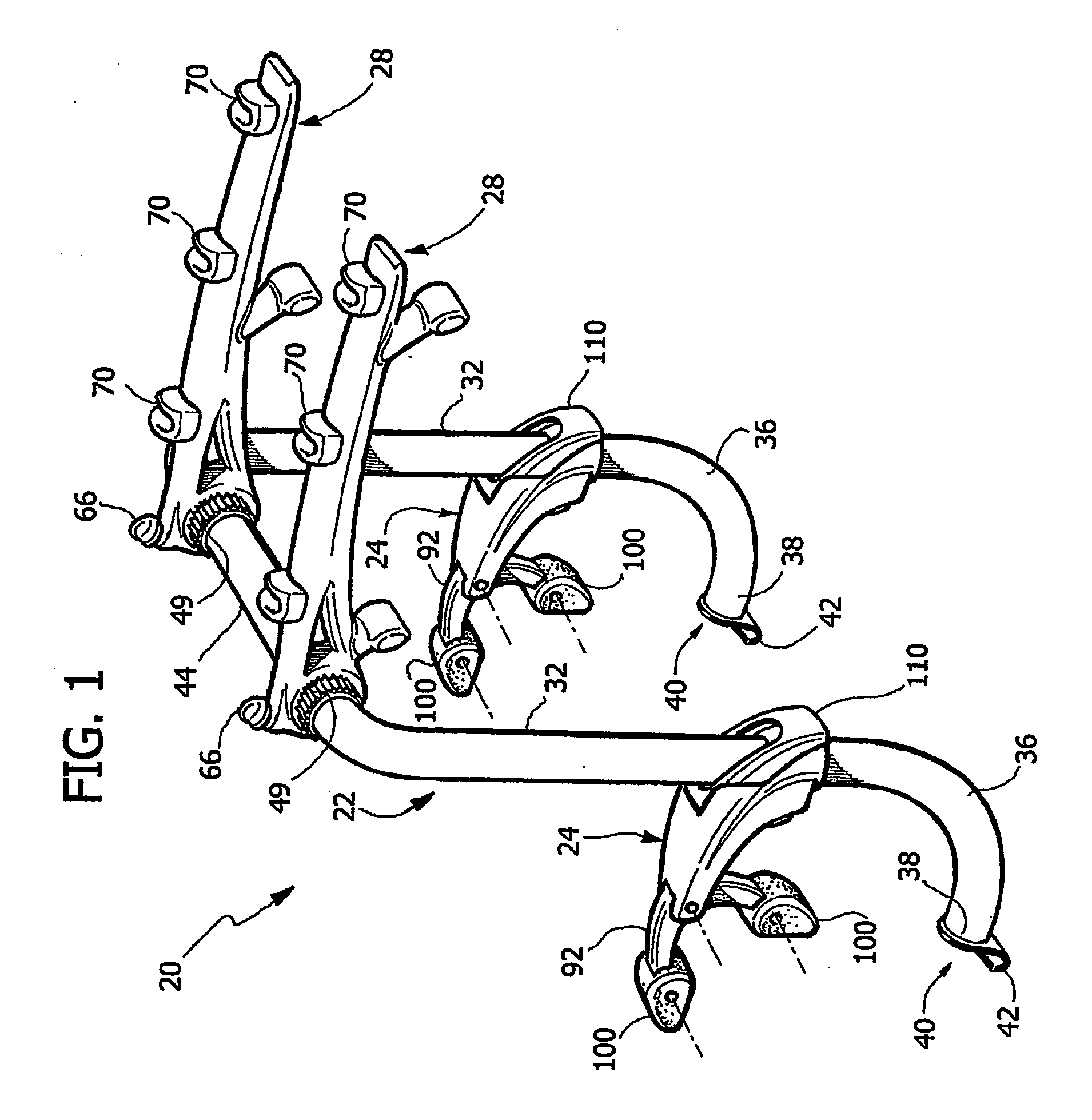
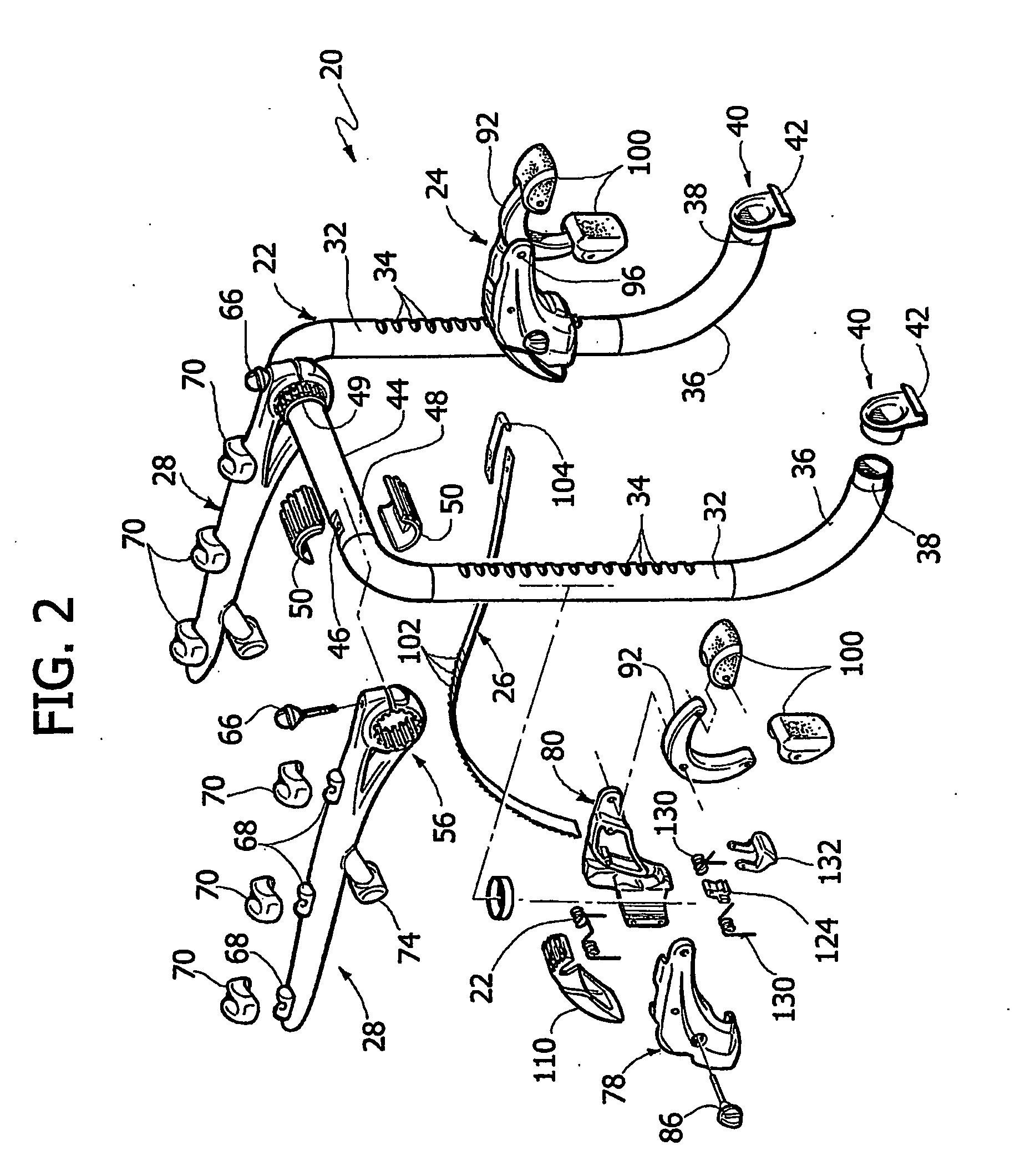
[0047] With reference to FIGS. 1-9, the invention is shown therein, in form of an equipment carrier 20 adapted for mounting to a vehicle for supporting various items on the exterior of the vehicle. Equipment carrier 20 generally includes a frame 22, a pair of supports 24 each of which includes a strap 26 (see in particular FIGS. 2,3,7), and a load-carrying arrangement engaged with frame 22, e.g. a pair of support arms 28.

[0048] In the illustrated embodiment, frame 22 includes a pair of upright sections 32 having forwardly facing spaced indentations 34. A curved lower section 36 extends from the lower end of each upright section 32, and terminates in a forwardly facing end 38. An engagement member 40, which includes a hook 42 at its lower end, is engaged with the forwardly facing end 38 of each lower section 36.

[0049] A cross-member 44 extends between and interconnects the upper ends of upright sections 32. Cross-member 44 includes provisions for mounting the equipment-carrying comp...

second embodiment

[0071] With reference to FIGS. 15-26 the invention is shown therein. In these figures, parts corresponding to those of FIGS. 1-14 are designated by the same reference numerals.

[0072] With reference in particular to FIGS. 17, 18, a main difference with respect to the carrier of the first embodiment lies in that each of the two straps 26 is stored in a wound configuration within the body of the respective support 24 when not in use.

[0073] With reference to FIG. 17, engagement member 40 includes a sleeve portion 41 which is freely rotatably mounted around the lower end 38 of the respective upright section 32. A rivet 420 (see FIG. 27) has its ends secured to two facing circular holes 422, one of which is formed at the top of sleeve portion 41, the other being formed in a tab 423 which is cut and bent away from the front wall of element 40 so as to engage the end portion 38 of the frame tube from below. The rivet is also engaged through two facing slots 421 formed on the upper and lowe...


PUM


Abstract

An equipment carrier for mounting onto a rear component of a vehicle structure, such as a vehicle trunk lid or door, comprises a frame having lower engagement elements engageable with a lower area of the vehicle component, a structure connected to the frame for carrying one or more items of equipment, at least one vehicle engaging member, connected to the frame, for engaging the vehicle component at a position above said lower area, a strap member having upper engagement elements for engagement with an upper area of the vehicle component, and at least one support connected to the frame, provided with a strap engaging and tensioning mechanism, which is engaged by the strap member and can be controlled for tensioning the strap member in order to tighten the upper and lower engagement elements onto the upper and lower areas of the vehicle component.

Description

BACKGROUND OF THE INVENTION [0001] The present invention relates to equipment carriers, such as carriers for bicycles, skis, luggage or the like, which are to be mounted onto a vehicle trunk lid or door. [0002] Carriers of this type are encountering increasing favour among users with respect to carriers which are to be mounted on the vehicle roof, also due to the inconvenience of placing the equipment (e.g. a bicycle) on the vehicle roof, particularly with relatively tall vehicles such as Sport Utility Vehicles (SUV), vans or others. [0003] It is particularly important for an equipment carrier of the type to be mounted on a trunk lid or door that it can be mounted and removed with very quick and simple operations by the user. Equipment carriers of this type which have been proposed heretofore are not able to solve this problem very satisfactorily. A conventional equipment carrier for mounting on a vehicle trunk lid or door comprises a frame with a structure for carrying one or more ...

Claims


Application Information

Patent Timeline
Patent Type & Authority Applications(United States)
IPC IPC(8): B60R11/00B60R9/00B60R9/06
CPCB60R9/06B60R9/10Y10S224/924B60R9/12
Inventor PEDRINI, FABIO
Owner PEDRINI
Why Eureka
Try Eureka