Suspension assembly

a suspension system and golf bag technology, applied in the field of manual operation (nonmotorised) golf buggies, can solve the problems of golf bag rattles, golf clubs are difficult or uncomfortable for players to manoeuvre, and the impact of golf bag clubs is potentially damaging, etc., to achieve the effect of simple yet surprisingly effective suspension system, easy integration into the manufacture of golf buggies, and aesthetics acceptabl

Inactive Publication Date: 2006-06-29
UNDER PAR
View PDF10 Cites 2 Cited by
  • Summary
  • Abstract
  • Description
  • Claims
  • Application Information

AI Technical Summary

Benefits of technology

[0017] Using the present invention, it is possible to provide golf buggies with a simple yet surprisingly effective suspension system. The simplicity of its design allows the system to be relatively inexpensive, aesthetically acceptable and easily incorporated into the manufacture of buggies, or as an after market retrofit. The cushioned ride provided by the suspension significantly reduces the potentially damaging rattling of the clubs in the bag. The erratic or “jerky” movements of the buggy handle as it is drawn over rough ground is also substantially diminished. In turn, the ease and comfort of manoeuvring the buggy is enhanced.

Problems solved by technology

Unfortunately, irregularities in the ground surface are translated directly to the golf buggy handle.
This can make manoeuvring difficult or uncomfortable for the player.
Ground irregularities will also cause the clubs in the golf bag to rattle against each other with potentially damaging impact.
Such rattling also generates an appreciable level of noise which can be distracting and disruptive to other players on the course.

Method used


Image

  • Suspension assembly
  • Suspension assembly
  • Suspension assembly

Examples


Embodiment Construction

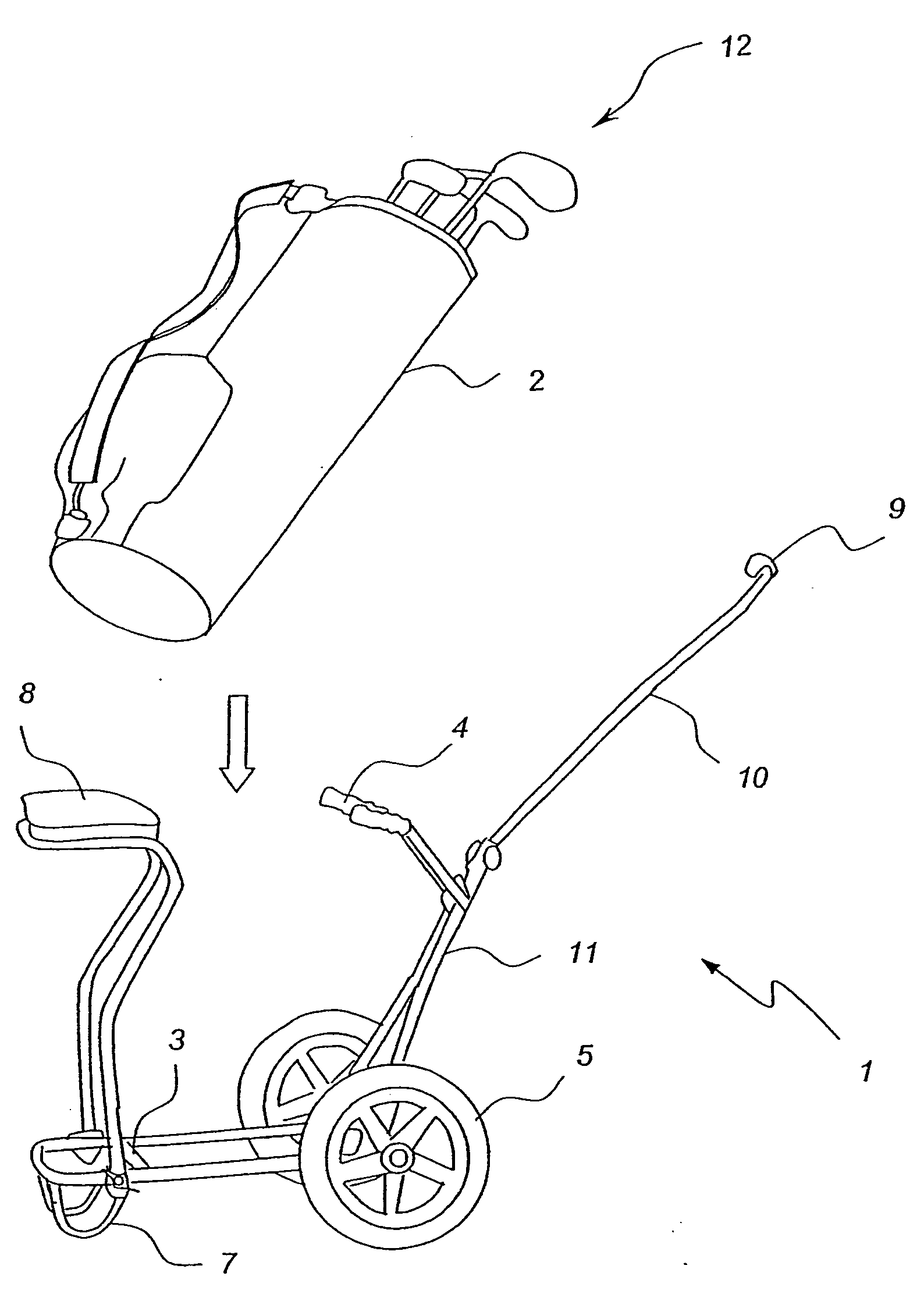
[0023] The golf buggy 1 shown in FIG. 1 is typical of most manually drawn golf buggies. The golf bag 2 is craddled in the buggy against a bag support 3 and craddle arms 4. The bag 2 is craddled so that its weight allows the buggy to stay upright and supported on the wheels 5 and 6 as well as the support 7. Often, a seat 8 is also provided for the comfort of the player.

[0024] In use, the player draws the buggy along using the handle 9. The length of the handle stem 10 is designed so that the chassis 11 of the buggy 1 rotates about the axis of the wheels to disengage the support 7 from the ground.

[0025] The wheels 5 and 6 are rigidly mounted to the chassis 11 and any shocks or vibrations caused by irregularities in the ground surface are transmitted directly to the golf bag 2 and the handle 9. This can shake the bag 2 and cause the clubs 12 to impact with each other and the interior of the bag. This is potentially damaging to the clubs and generates a significant level of noise.

[00...


PUM


Abstract

A suspension assembly adapted to be fitted to a manually drawn two wheeled golf buggy includes a chassis mount typically arranged to be mounted into the existing axle tube of a conventional golf buggy by way of a spigot, a scissor link in the form of a chassis mount arm extending from the chassis mount and a wheel mount arm pivotally connected together by hinge arrangement, and a wheel mount sleeve adapted to receive the stub axle of a golf buggy wheel. A compression spring is provided between the chassis mount and the wheel mount allowing for damp resilient movement between the wheel of the golf buggy and the chassis. Variations are also described where the suspension assembly is provided as an integral part of the golf buggy chassis.

Description

FIELD OF THE INVENTION [0001] The present invention relates to manually operated (non-motorised) golf buggies of the type used to carry a player's golf bag around the course. BACKGROUND OF THE INVENTION [0002] Golf buggies generally have a chassis with two wheels arranged so that it can cradle a golf bag and support itself in a stable, upright position. To move the buggy around the course, the chassis is rotated about the axis of the wheels so that the supporting section of the chassis lifts off the ground thus freeing the wheels to roll as it is drawn along behind or pushed by the player. [0003] Unfortunately, irregularities in the ground surface are translated directly to the golf buggy handle. This can make manoeuvring difficult or uncomfortable for the player. Ground irregularities will also cause the clubs in the golf bag to rattle against each other with potentially damaging impact. Such rattling also generates an appreciable level of noise which can be distracting and disrupt...

Claims


Application Information

Patent Timeline
Patent Type & Authority Applications(United States)
IPC IPC(8): B62B1/00A63B55/60B62B1/04B62B5/08
CPCB62B1/042B62B5/085B62B2202/404B62B2301/20
Inventor CLAREBROUGH, BRETT JOHNHYDE, DOUGLAS GORDON
Owner UNDER PAR
Why Eureka
Try Eureka