Reproduction apparatus and decoding control method

a technology of decoding control and reproduction apparatus, which is applied in the field of decoding control method of reproduction apparatus, can solve the problems of differing delay time, difficult to make use of clock adjustment, and inapplicability of apparatus

Inactive Publication Date: 2006-06-29
KK TOSHIBA
View PDF8 Cites 61 Cited by
  • Summary
  • Abstract
  • Description
  • Claims
  • Application Information

AI Technical Summary

Benefits of technology

The present invention provides a device for playing back video streams that have been compressed. This includes a system for detecting when the video is being played in real-time (when it needs to be processed quickly) or on demand (when it doesn't require such fast processing). When the video is playbacked in real-time mode, the system adjusts its timing accordingly to ensure smooth playback. On the other hand, when the video is playbacked in on-demand mode, the system uses a constant timer to keep track of how much content has been added to the buffer since the last fix. By monitoring this, the system ensures that the video plays without interruption even after some delay between recording and playback.

Problems solved by technology

The technical problem addressed in this patent relates to ensuring proper timing and synchronization during the transfer of media files or streaming data over networks. Clock controls are used to ensure that the receiving device's clock matches the sender's clock, allowing for seamless playback without errors or delays. However, these controls must account for differences in latency caused by varying network conditions, making it challenging to maintain optimal performance. Additionally, some applications require faster or slower rates of data transfer depending on their specific needs, further complicating the synchronization process.

Method used


Image

  • Reproduction apparatus and decoding control method
  • Reproduction apparatus and decoding control method
  • Reproduction apparatus and decoding control method

Examples


Embodiment Construction

[0033] An embodiment according to the present invention will now be described with reference to the accompanying drawings.

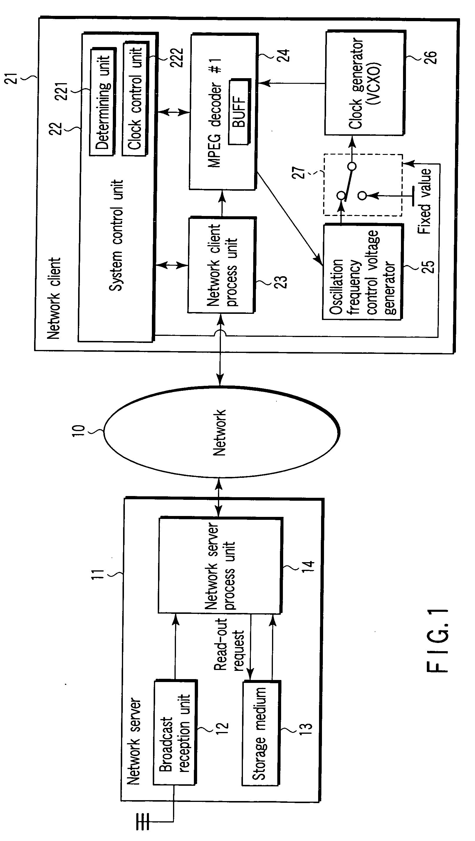
[0034]FIG. 1 shows a configuration of a reproduction apparatus according to an embodiment of the present invention. The reproduction apparatus is realized as a network client 21 that can execute communication with a network server 11. The network server 11 and network client 21 are connected to a network 10 such as a household LAN (Local Area Network). The network server 11 functions as a server of a home network system. The network client 21 functions as a client terminal of the home network system.

[0035] The network server 11, as shown in FIG. 1, comprises a broadcast reception unit 12, a storage medium 13 and a network server process unit 14. The broadcast reception unit 12 is a reception apparatus that receives broadcast program data such as a TV program. The broadcast reception unit 12 receives a digital broadcast signal such as a terrestrial digital broad...


PUM


Abstract

A reproduction apparatus includes a unit which receives a stream that is transferred from a server, a buffer which stores the received stream, a decoder which executes a decoding process for reading out the received stream from the buffer and decoding the received stream, a clock generator which generates a clock signal which determines a speed of the decoding process, a unit which determines whether the received stream is a real-time stream or a non-real-time stream, and a unit which executes a process for varying a frequency of the clock signal in accordance with a fill level of the buffer if the received stream is the real-time stream, and executes a process for setting the frequency of the clock signal at a fixed value if the received stream is the non-real-time stream.

Description


Claims


Application Information

Patent Timeline
Owner KK TOSHIBA
Why Eureka
Try Eureka