
Flat panel speaker, electronic device having same, and structure and method for mounting same

a technology of electronic devices and diaphragms, which is applied in the direction of diaphragm construction, piezoelectric/electrostrictive transducers, transducer types, etc., can solve the problems of insufficient amount of voice, unclear voice, and difficulty for users to put the voice hole on their/her ear,

Inactive Publication Date: 2006-06-29
LENOVO INNOVATIONS LTD HONG KONG
View PDF1 Cites 44 Cited by
  • Summary
  • Abstract
  • Description
  • Claims
  • Application Information

AI Technical Summary

Benefits of technology

[0016] In view of the above, it is an object of the present invention to provide a structure and method for mounting a flat panel speaker which are capable of reliably and accurately positioning a diaphragm relative to a cabinet and of improving an acoustic characteristic of the flat panel speaker, the flat panel speaker used in the above structure and method, the diaphragm making up the flat panel speaker, and the electronic device in which the flat panel speaker is mounted.
[0050] Also, a preferable mode is one wherein the supporting member includes a flat and frame-shaped component and is placed so that its inner wall face surrounds the aperture and has a foreign-matter entry preventing function of preventing entry of a foreign matter including dust from the aperture into the cabinet.
[0064] Also, a preferable mode is one wherein the supporting member includes a flat and frame-shaped component and is placed so that its inner wall face surrounds the aperture and has a foreign-matter entry preventing function of preventing entry of a foreign matter including dust from the aperture into the cabinet.
[0089] Also, a preferable mode is one wherein the supporting member includes a flat and frame-shaped component and is placed so that its inner wall face surrounds the aperture so as to prevent the entry of a foreign matter including dust from the aperture into the cabinet.
[0093] With the above configurations, by striking of the first protruding portion against the first struck portion, the diaphragm is properly positioned relative to the cabinet along the first direction and, by striking of the second protruding portion against the second struck portion, the diaphragm is properly positioned relative to the cabinet along the second direction and the diaphragm comes into contact with the cabinet only in a contacted portion between the first protruding portion and the first struck portion and only in a contacted portion between the second protruding portion and the struck portion in a state in which the diaphragm is properly positioned relative to the cabinet and is attached to the cabinet and, therefore, a region in which a side surface of the diaphragm is pressed by the cabinet is reduced greatly, which enables suppression of interference with vibration of the diaphragm caused by the cabinet, thus making it possible to reliably and accurately position the diaphragm relative to the cabinet and, as a result, to improve an acoustic characteristic of the flat panel speaker.

Problems solved by technology

However, the conventional portable cellular phone 101 has a problem.
Moreover, the user, when carrying out a telephone conversation, puts the speaker section 106 on his / her ear with the cabinets 105, 108 being opened, however, since a voice hole of the speaker section 106 is comparatively small, it is difficult for the user to put the voice hole on his / her ear exactly and the portable cellular phone 101 is displaced from a position of the voice hole, as a result, causing an insufficient amount of a voice and an unclear voice.
A problem of the conventional technology to be solved is that the cabinet of the portable cellular phone 101 comes into contact with a side surface of the diaphragm 202 over a wide range of regions and, as a result, presses a side surface of the diaphragm 202, thus causing interference with vibration of the diaphragm 202 and degradation of an acoustic characteristic of the flat panel speaker 201.
As a result, the side surfaces of the diaphragm 202 are pressed by the front case 206, causing interference with vibration of the diaphragm 202, thus effecting adversely acoustic characteristics (in terms of degradation of voice quality and decrease in voice volume (sound level)).

Method used


Image

  • Flat panel speaker, electronic device having same, and structure and method for mounting same
  • Flat panel speaker, electronic device having same, and structure and method for mounting same
  • Flat panel speaker, electronic device having same, and structure and method for mounting same

Examples


embodiment

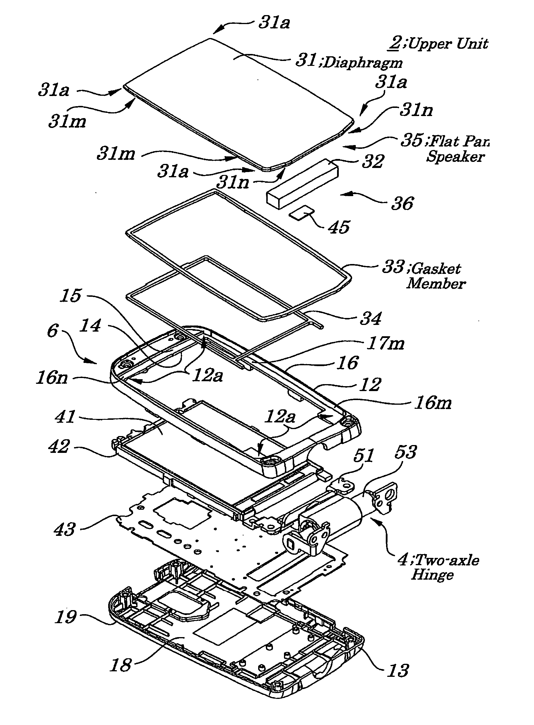
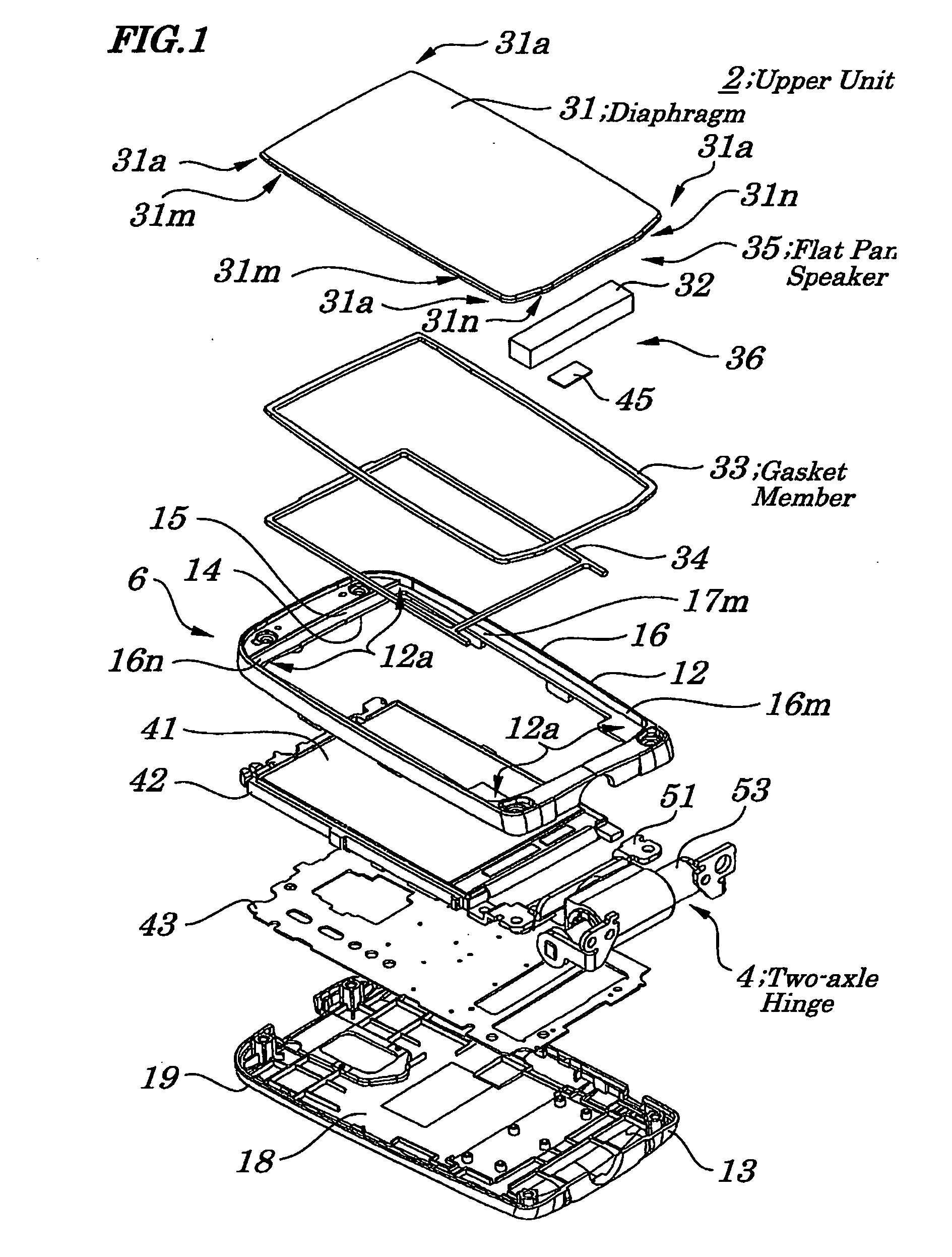
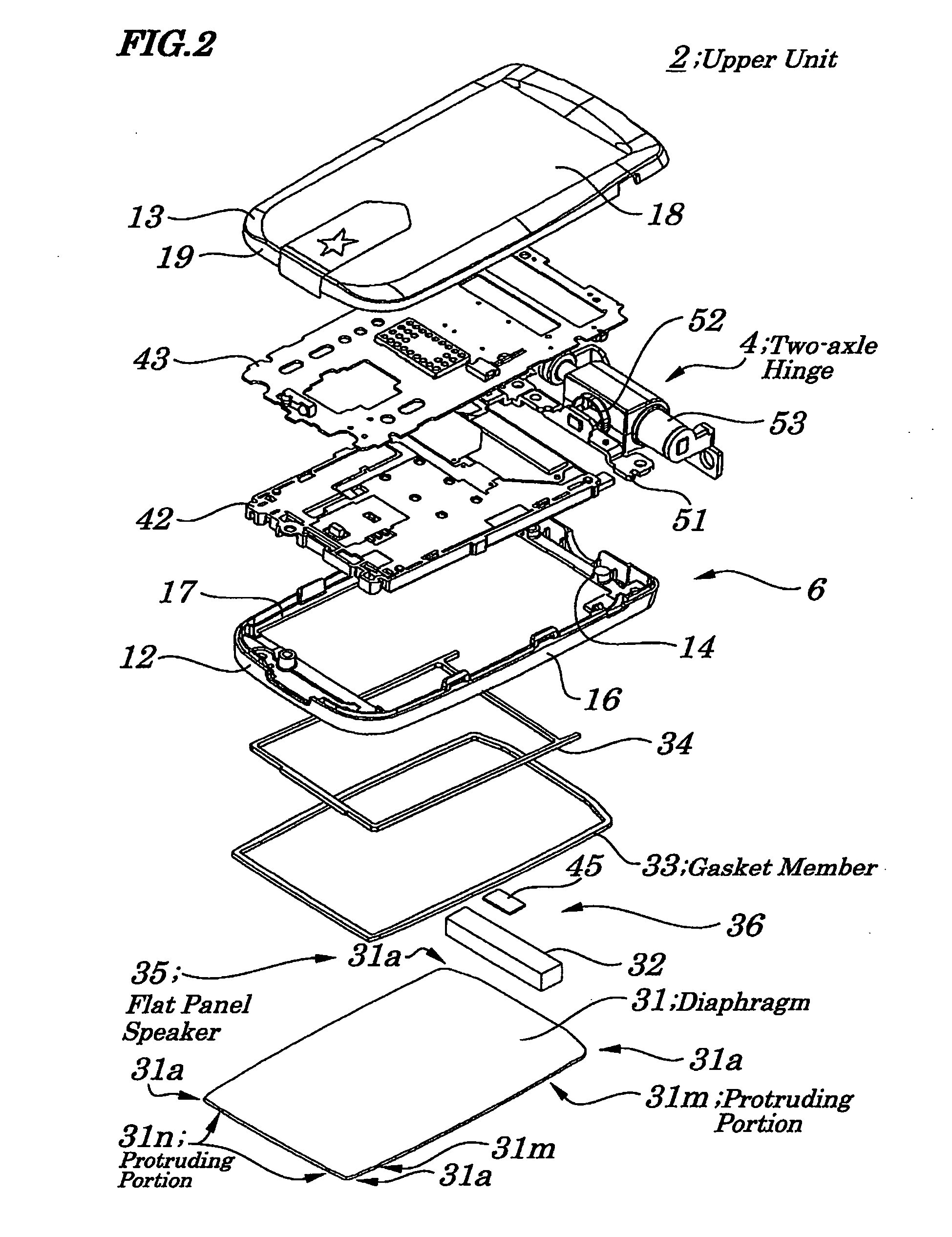
[0121]FIG. 1 is an exploded perspective view showing configurations of an upper unit 2 obtained by disassembling the upper unit 2 of a portable cellular phone 1 and by viewing the upper unit from its front side according to an embodiment of the present invention. FIG. 2 is an exploded perspective view showing configurations of the upper unit 2 obtained by disassembling the upper unit 2 of the portable cellular phone 1 and by viewing the upper unit 2 from its rear side according to the embodiment. FIG. 3 is a block diagram showing configurations of the portable cellular phone 1 according to the embodiment. FIG. 4 is a plan view showing configurations of the upper unit 2 of the portable cellular phone 1 according to the embodiment. FIG. 5 is a cross-sectional view of the upper unit 2, taken along a line A-A of FIG. 4. FIG. 6 is a cross-sectional view of the upper unit 2,-taken along a line B-B of FIG. 4. FIG. 7 is a perspective view showing configurations of a diaphragm 31 of a voice ...


PUM


Abstract

A structure and method for mounting a flat panel speaker are provided which are capable of reliably and accurately positioning a diaphragm in a cabinet and of improving an acoustic characteristic of the flat panel speaker. At least one first protruding portion formed in rectangular portions strikes a first side wall face of a corresponding corner portion of two side walls making up a front case and at least one second protruding portion formed in rectangular portions strikes a second side wall face of a corresponding corner portion of another side wall face of the front case, thus making it possible to properly position the diaphragm relative to the front case and, with the diaphragm being properly positioned, the diaphragm is attached to the front case with the gasket member bonded to the putting-face interposed between the diaphragm and the front case. The diaphragm comes into close contact with the front case in a manner to form a line-like boundary in a contacted portion.

Description

BACKGROUND OF THE INVENTION [0001] 1. Field of the Invention [0002] The present invention relates to a diaphragm, the flat panel speaker, an electronic device provided with the same flat panel speaker, and a structure and method for mounting the same flat panel speaker, and more particularly to the structure and method for mounting the flat panel speaker employed in the electronic device in which the diaphragm serving also as a screen component is attached to a cabinet including an electronic device such as a foldable-type portable cellular phone using the screen component to protect a display panel as the diaphragm to emit a voice, and to the flat panel speaker used in the above structure and method, the diaphragm making up the flat panel speaker, and the electronic device in which the flat panel speaker is mounted. [0003] The present application claims priority of Japanese Patent Application No. 2004-380304 filed on Dec. 28, 2004, which is hereby incorporated by reference. [0004] ...

Claims


Application Information

Patent Timeline
IPC IPC(8): H04R11/02
CPCH04M1/03H04M1/72519H04R2499/11H04R7/04H04R17/00H04R1/025H04M1/724
Inventor KIMURA, YUUICHIROUYAMAMOTO, ATSUSHI
Owner LENOVO INNOVATIONS LTD HONG KONG
Features
  • Generate Ideas
  • Intellectual Property
  • Life Sciences
  • Materials
  • Tech Scout
  • Unparalleled Data Quality
  • Higher Quality Content
  • 60% Fewer Hallucinations
Learn More