Glass tube for technical applications and process for the production thereof

a technology of glass tubes and glass tubes, applied in glass blowing apparatus, glass shaping apparatus, drinking vessels, etc., can solve the problems of crack formation and switch destruction, and achieve the effect of convenient and cost-effectiveness

Inactive Publication Date: 2006-06-29
SCHOTT AG
View PDF3 Cites 23 Cited by
  • Summary
  • Abstract
  • Description
  • Claims
  • Application Information

AI Technical Summary

Benefits of technology

[0011] The object of the present invention is to provide a glass tube for technical applications, especially for electrical or magnetic components, for example for electronic components, with which it is p

Problems solved by technology

At the same time, unavoidable axial and tangential tensile stresses arise which lead to

Method used


Image

  • Glass tube for technical applications and process for the production thereof
  • Glass tube for technical applications and process for the production thereof
  • Glass tube for technical applications and process for the production thereof

Examples


Embodiment Construction

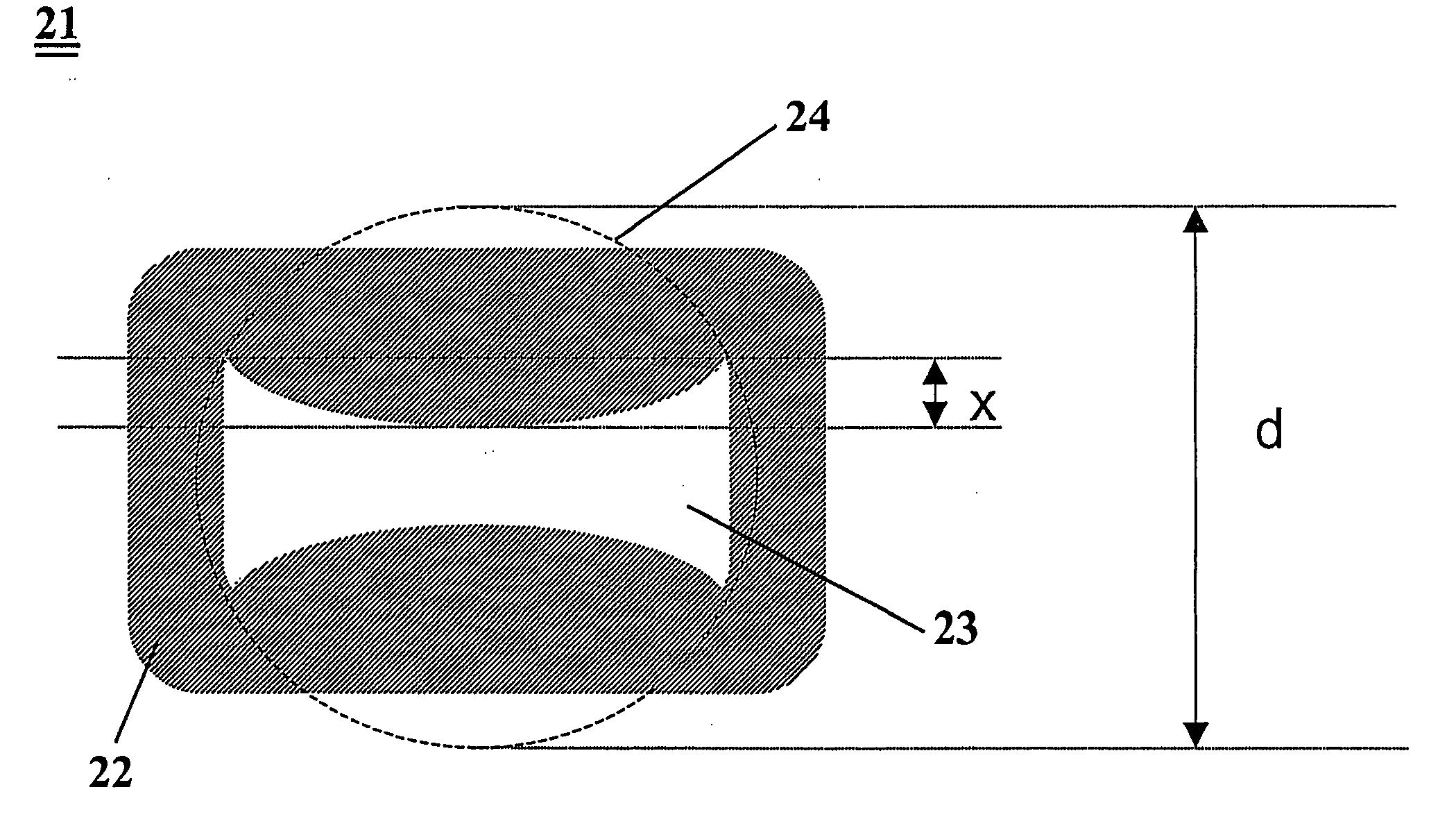
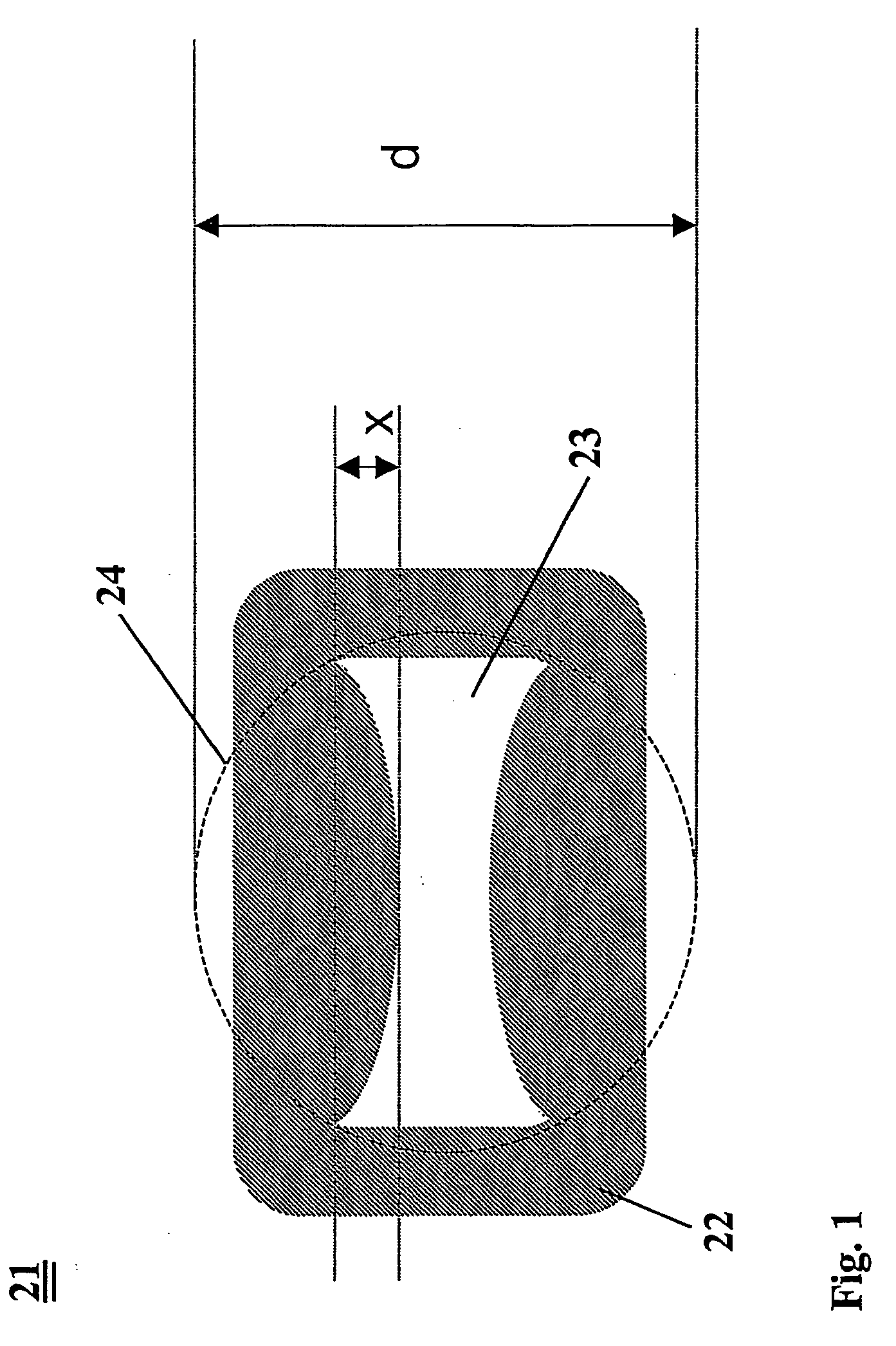
[0036] According to FIG. 1, glass tube 21 has a substantially rectangular-shaped outer profile which is formed from four tube walls. The two lateral tube walls in the embodiment illustrated are flat and extend substantially parallel to each other over the entire height of glass tube 21. The opposing upper and lower tube walls have a cross-sectional constriction on their respective inner circumferential wall which narrows inner bore 23 of glass tube 21.

[0037] According to FIG. 1, the two corresponding cross-sectional constrictions are formed as convex bulges projecting inwards in the shape of menisci. In the direction of the width of glass tube 21, the cross-sectional constrictions have a continuous, smooth course. The cross-sectional constrictions cut the two side walls at respective corner points of inner bore 23 or of the inner profile. These four corner points define circumference 24 marked schematically by a dotted line, the diameter of which is designated with the variable d. ...


PUM

PropertyMeasurementUnit
Lengthaaaaaaaaaa
Lengthaaaaaaaaaa
Thicknessaaaaaaaaaa

Abstract

The invention relates to glass tubes for technical applications, especially for electrical or magnetic components, such as reed switches for example.
According to a first embodiment, the glass tube has an inner bore (23) and at least one cross-sectional constriction (X) whereby the relationship applicable between the respective cross-sectional constriction (X) and the diameter (d) of the circumference of inner bore (23) is: x greater than or equal to 0.02*d, more preferably x greater than or equal to 0.1*d. According to a further embodiment, the glass tube has at least one inner bore with at least one inner edge, wherein the radius of curvature of the respective inner edge is less than or equal to 0.1 mm and preferably less than or equal to 0.03 mm. The glass tube is used as a preform for a subsequent redrawing process. The preform is formed by casting a molten glass into a shaft in the interior of which is located a shaping means for defining the inner bore. In this case a gas cushion prevents direct contact of the molten glass with the inner circumferential wall of the shaft and/or the outer circumferential wall of the shaping means.

Description

FIELD OF THE INVENTION [0001] The present invention relates in general to glass tubes for technical applications, especially for electrical or magnetic components, and a process for the production thereof. In particular, the present invention relates to glass tubes for use as encapsulation for what are known as reed switches. BACKGROUND OF THE INVENTION [0002] Reed switches are known to be electronic switching components, the contacts of which are connected in a glass tube under a shielding gas atmosphere, an inert gas atmosphere or under vacuum and which are operated by external magnetic fields in order to perform a switching operation. For enclosure in the shielding gas atmosphere previously referred to, reed switches are usually encapsulated in a glass tube (frequently also referred to as a “reed tube” or “reed glass”) the ends of which ate appropriately sealed off. [0003] Reed switches of the type referred to above are used in large numbers wherever low switching capacity, high ...

Claims


Application Information

Patent Timeline
IPC IPC(8): C03B9/16C03B29/00B28B11/00
CPCC03B17/04C03B19/02C03B23/047Y10T428/131H01H1/66H01H11/005C03B40/04
Inventor LANGSDORF, ANDREASBUELLESFELD, FRANKLANGE, ULRICHZOETTL, MARTIN
Owner SCHOTT AG
Why Eureka
Try Eureka