Electrical connector

a technology of electrical connectors and connectors, applied in the direction of coupling device connections, incorrect coupling prevention, securing/insulating coupling contact members, etc., can solve the problem that the front holder b>8/b> that has to be removed temporally from the housing b>6/b> is liable to be los

Inactive Publication Date: 2006-06-29
FURUKAWA AUTOMOTIVE SYST +1
View PDF9 Cites 20 Cited by
  • Summary
  • Abstract
  • Description
  • Claims
  • Application Information

AI Technical Summary

Benefits of technology

[0010] According to the present invention, an electrical connector comprising a housing accommodating connecting terminals connected to distal ends of electric wires, said housing including locking arms for retaining said connecting terminals not to remove from a backside of the housing, and a front holder inserted into a front portion of the housing such that said locking arms are urged against the connecting terminals to enhance a locking force of the locking arms, characterized in that said front holder is movable with respect to said housing between a first position and a second position in a direction perpendicular to an axial line of the housing; in said first position of the front holder, terminal inserting holes formed in the front housing are aligned with axial lines of the connecting terminals installed within the housing such that upon engaging a cooperating housing with the housing, an electrical connection between the connecting terminals installed within the housing and associated connecting terminals installed within the cooperating housing is attained; and in said second position of the front holder, the terminal connecting holes are shifted out of the axial lines of the connecting terminals installed within the housing and arm operating holes formed in the front holder are aligned with the locking arms.
[0011] According to further aspect of the present invention, an electrical connector comprising a housing accommodating connecting terminals connected to distal ends of electric wires, said housing including locking arms for retaining said connecting terminals not to remove from a backside of the housing, and a front holder inserted into a front portion of the housing such that said locking arms are urged against the connecting terminals to enhance a locking force of the locking arms, characterized in that said front holder is movable with respect to said housing between a first position and a second position in a direction perpendicular to an axial line of the housing; in said first position of the front holder, a cooperating housing is engaged with the housing to establish an electrical connection between the connecting terminals installed within the housing and associated connecting terminals installed within the cooperating housing and locking lances are urged against the connecting terminals; and said front holder includes arm pushing portions for releasing said locking lances in said second position of the front holder.
[0012] According to another aspect of the present invention, an electrical connector comprising a housing accommodating connecting terminals connected to distal ends of electric wires, said housing including locking arms for retaining said connecting terminals not to remove from a backside of the housing, and a front holder inserted into a front portion of the housing such that said locking arms are urged against the connecting terminals to enhance a locking force of the locking arms, characterized in that said front holder is movable with respect to said housing between a first position and a second position in a direction perpendicular to an axial line of the housing; in said first position of the front holder, a cooperating housing is engaged with the housing to establish an electrical connection between the connecting terminals installed within the housing and associated connecting terminals installed within the cooperating housing; and said front holder includes terminal pushing portions for pushing the connecting terminals backward during movement of the front holder from the first position to the second position such that a space is not formed between the locking arms and the connecting terminals in an axial direction.

Problems solved by technology

In this manner, during the operation of removing one or more connecting terminals by releasing the engagement of the locking arm or arms, the front holder 8 that has to be removed temporally from the housing 6 is liable to be lost.

Method used


Image

  • Electrical connector
  • Electrical connector
  • Electrical connector

Examples


first embodiment

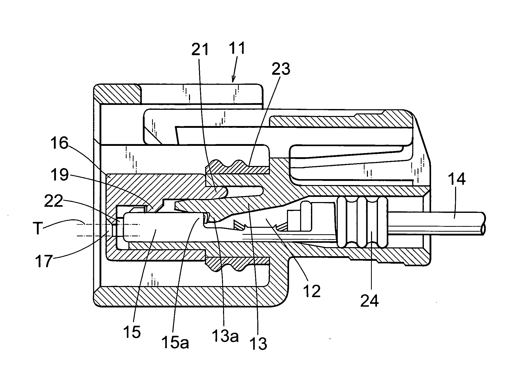
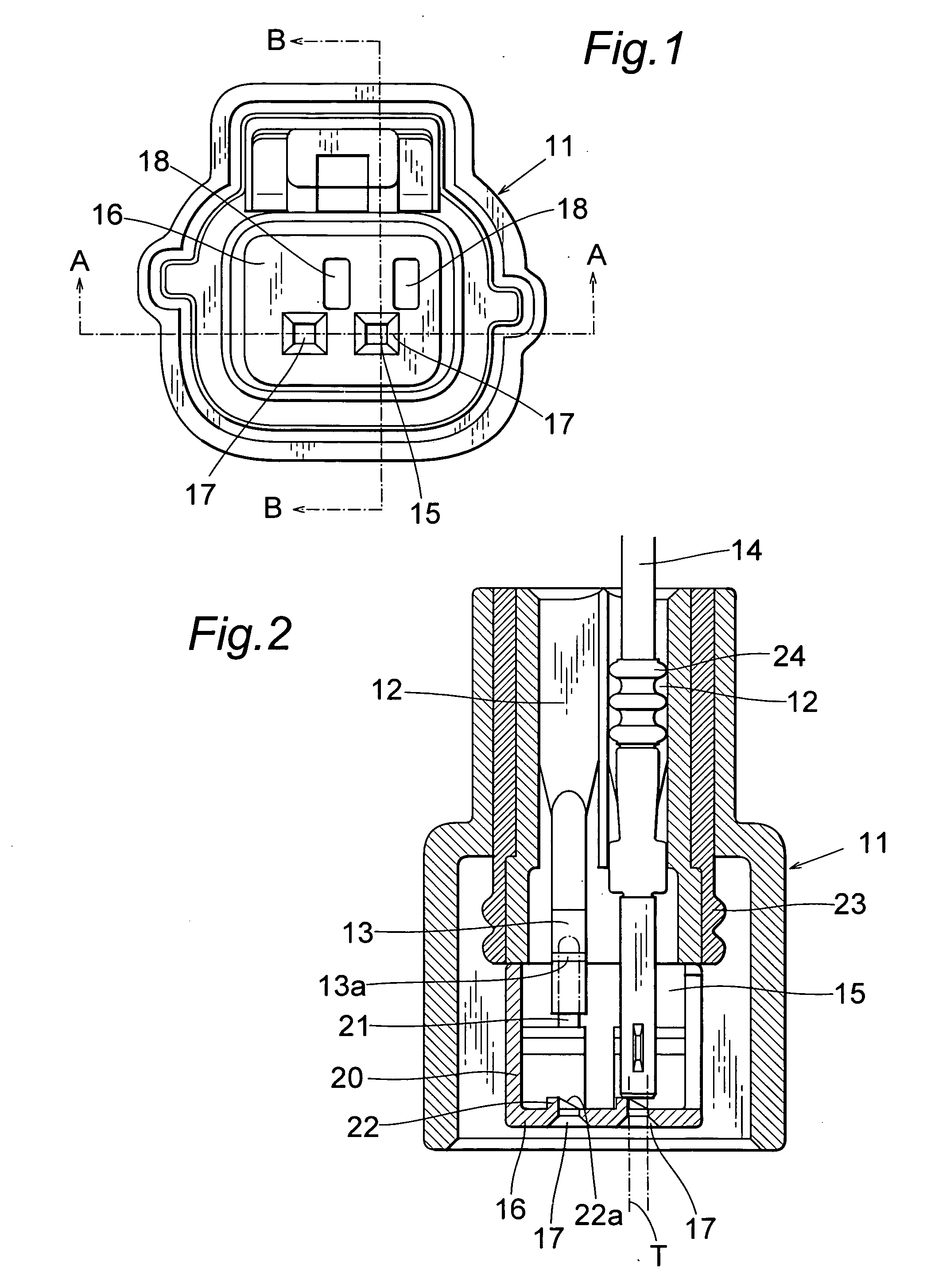
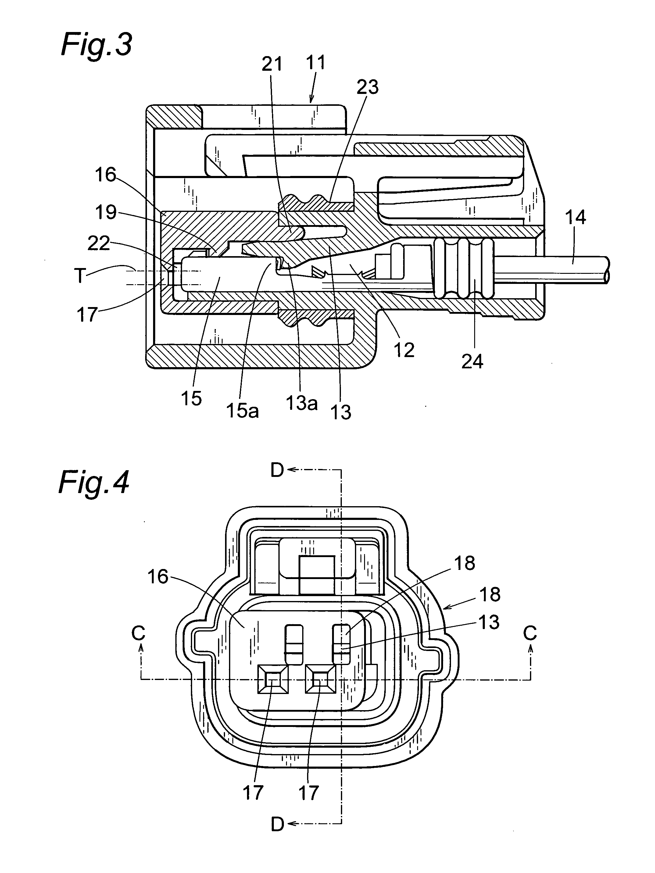
[0029]FIGS. 1-3 show the electrical connector according to the invention. FIG. 1 is a front view of a housing under a condition in which an associated housing may be engaged, FIG. 2 is a cross sectional view of the housing and front holder cut along an A-A line in FIG. 1, and FIG. 3 is a similar cross sectional view cut along a B-B line in FIG. 1.

[0030] Within a housing 11 made of a synthetic resin there are formed two terminal accommodating holes 12 and two locking arms 13 in which a resilient force is provided downward are formed above the respective terminal accommodating holes 12. Within the terminal accommodating holes 12, female-type connecting terminals 15 having electric wires 14 connected thereto are inserted from a rear side of the housing 11 such that rear ends of connecting portions 15a of the connecting terminals 15 are engaged with claw portions 13a of the locking arms 13 to prevent undesired removal of the connecting terminals 15 in the backward direction. It should b...

second embodiment

[0046]FIGS. 11 and 12 illustrate the electrical connector according to the invention. FIG. 11 is a front view of the connector under a condition that associated or cooperating connecting terminals may be inserted, and FIG. 12 is a longitudinal cross sectional view.

[0047] Within a housing 31 made of a synthetic resin there are formed, for instance two terminal accommodating holes 32 arranged side by side, and two locking arms 33 are formed above the respective terminal accommodating holes 32, said locking arms 33 being resiliently deformed upward. Within the terminal accommodating holes 32, female-type connecting terminals 35 having electric wires 34 connected thereto are inserted from a rear side of the housing 31 such that rear portions of connecting portions 35a of the connecting terminals 35 are engaged with claw portions 33a of the locking arms 33 to prevent undesired removal of the connecting terminals 35 in the backward direction.

[0048] A front holder 36 made of a synthetic r...


PUM


Abstract

Upon releasing a locking arm from a connecting terminal by inserting a jig through a front holder, the jig could not be erroneously inserted into a terminal inserting hole. Connecting terminals 15 are inserted into a housing 11, and the connecting terminals are prevented from being pulled out of the housing backwardly by means of locking arms 13 arranged above the respective connecting terminals 15. The front holder is engaged with the housing by a clamping mechanism in an axial direction and is movable laterally in a direction perpendicular to the axial direction. A pair of a terminal inserting hole 17 and an arm operating hole 18 provided for respective connecting terminals are shifted laterally. In a first position of the front holder 16, the terminal inserting hole 17 is aligned with an axial line of a female-type connecting terminal 15, but the arm operating hole 18 is shifted laterally from the locking arm.

Description

TECHNICAL FIELD [0001] The present invention relates to an electrical connector for use in, for example wire harnesses of automobiles. TECHNICAL BACKGROUND [0002] (1) In a known electrical connector of the kind mentioned above, a plurality of connecting terminals each being connected to distal ends of respective electric wires are installed within a housing, and the connecting terminals are retained within the housing by means of locking arms formed integrally with the housing. Locking force of the locking arms can be positively enhanced by inserting a front holder 1 into a front portion of the housing as shown in FIG. 15. [0003] In this case, when it is required to remove a connecting terminal from the housing 2, it is necessary to release a locking operation of an associated locking arm with the relevant connecting terminal. To this end, arm operating holes 4 through which a suitable jig may be inserted into the housing 2 from a front side thereof are formed in the front holder 1 ...

Claims


Application Information

Patent Timeline
Patent Type & Authority Applications(United States)
IPC IPC(8): H01R13/40H01R13/422H01R13/436H01R43/26
CPCH01R13/4223H01R13/4365H01R43/26H01R13/64
Inventor MACHIDA, YUKIFUMIYAMAGUCHI, SHINJITANAKA, YOSHIKAZUHIGUCHI, TAKAYUKI
Owner FURUKAWA AUTOMOTIVE SYST
Why Eureka
Try Eureka