Electric connector permitting testing of electric conductivity of terminals in provisional locking position

a technology of electric conductivity and electric connector, which is applied in the direction of securing/insulating coupling contact members, coupling device connections, electrical apparatus, etc., can solve the problems of insufficient simplified structure of molds or tools for manufacturing rear holder, liable to be complicated in construction, and the complexity of molds for manufacturing the housing

Inactive Publication Date: 2003-03-20
FURUKAWA AUTOMOTIVE SYST +1
View PDF0 Cites 11 Cited by
  • Summary
  • Abstract
  • Description
  • Claims
  • Application Information

AI Technical Summary

Problems solved by technology

Therefore, the housing including the locking arms is liable to be complicated in construction, and a mold for manufacturing the housing becomes very complicated and expensive.
However, in the known electrical connector, since the rear holder c includes the rectangular hollow portions f, a structure of a mold or tool for manufacturing the rear holder could not be simplified sufficiently.
That is to say, the mold must be constructed to have one or more bushings and still has a complicated structure.
When it is required to release a locking condition between a lo

Method used


Image

  • Electric connector permitting testing of electric conductivity of terminals in provisional locking position
  • Electric connector permitting testing of electric conductivity of terminals in provisional locking position
  • Electric connector permitting testing of electric conductivity of terminals in provisional locking position

Examples


first embodiment

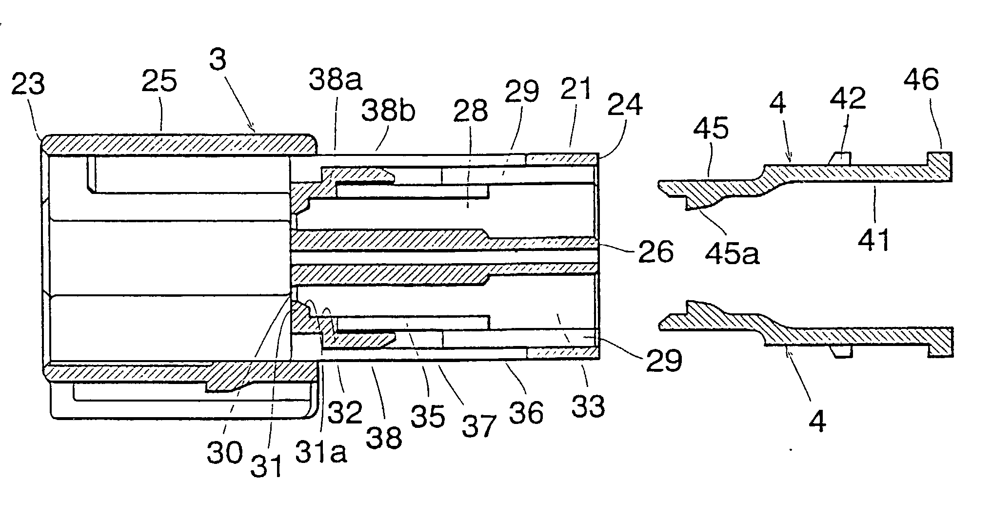
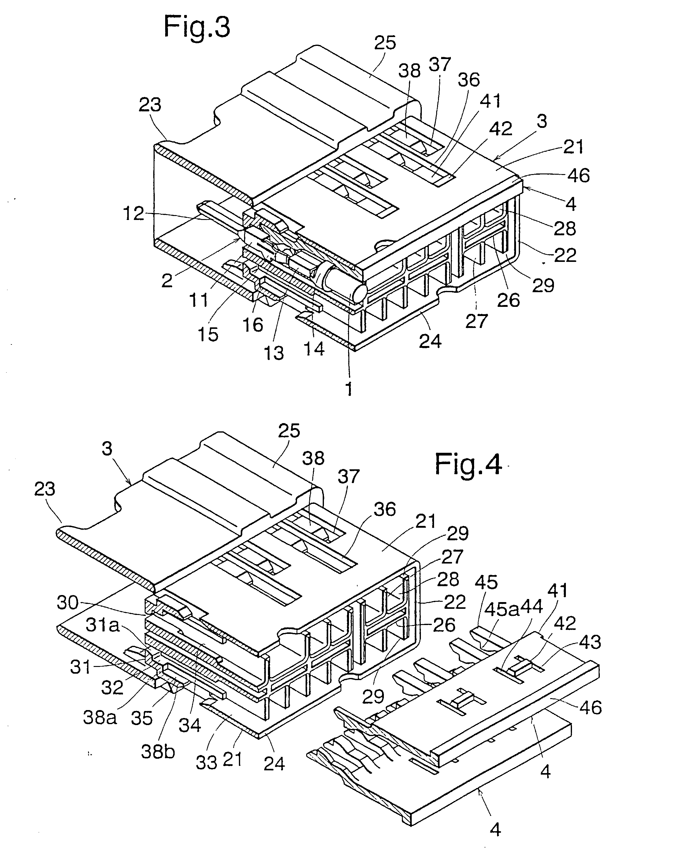
[0044] FIG. 3 is a perspective view showing the electrical connector according to the invention in an assembled form. Male type connecting terminals 2 having electric conductors 1 connected to rear portions thereof are accommodated within a housing 3, and the connecting terminals 2 are locked by a rear holder 4 which is engaged with a rear portion of the housing 3. FIG. 4 is an exploded perspective view of the electrical connector from which the connecting terminals 2 are removed, and FIG. 5 is an exploded perspective view corresponding to FIG. 2.

[0045] The connecting terminal 2 is formed from a single electrically conductive metal plate and includes a terminal main body 11 formed in a shape of a rectangular hollow member and a terminal connecting portion 12 provided at a front end of the terminal main body, said terminal connecting portion 12 being formed in a flat blade which can be connected to a female type connecting terminal of a corresponding electrical connector not shown. A...

second embodiment

[0059] FIG. 19 is a perspective view showing the electrical connector according to the invention in an assembled condition, while parts of the connector are cut off. In this embodiment, female type connecting terminals 6 having electric wires 5 connected to their rear ends are accommodated within a housing 7 and are locked in position by means of a rear holder 8 engaged with the rear portion of the housing 7. FIG. 19 is an exploded perspective view showing the connector while the connecting terminals 6 are removed, and FIG. 20 is an exploded perspective of the connector with the connecting terminals 6. At a rear portion of a rectangular hollow terminal main body 61 of a connecting terminal 6 there are provided a core wire clamping portion 62 and a sheath clamping portion 63. Within the terminal main body 61 there are provided a fixed contacting member 64 which can be urged against a male type connecting terminal of a corresponding connector not shown, and a movable contact 65. On an...


PUM


Abstract

A rear holder 4 is inserted into a housing 3 from a rear end surface 24 at a provisional locking position in which the rear holder 4 is inserted into the housing 3 halfway and an insertion of connecting terminals is allowed, as well as at a sufficiently inserted complete locking position at which the inserted connecting terminals are locked. Within the housing 3, there are formed two rows of terminal accommodating holes 28 each accommodating respective connecting terminals. The rear holder 4 is formed in a substantially plate-like shape and includes a main body 41 which is inserted into slits 29 of the housing 3 and locking arms 45 which are inserted into respective terminal accommodating holes 28. A width of a locking arm 45 is slightly smaller than that of a terminal accommodating hole 28. Windows 37 are formed in the outer wall 21 of the housing 3 such that the terminal accommodating holes 28 are communicated with external through the windows 37. Through these windows 37, locking condition between the connecting terminals 2 and the locking arms 45 can be released and an electrical conduction test of the connecting terminals 2 can be performed.

Description

[0001] The present invention relates to an electrical connector, which may be used for a wire harness in automobiles, and more particularly relates to an electrical connector, in which connecting terminals contained in a housing are locked by a rear holder which is engaged with a rear portion of the housing.[0002] FIG. 1 is a longitudinal cross sectional view showing a part of a known electric connector;[0003] FIG. 2 is an exploded perspective view of the known connector, while a part of the electric connector is cut out;[0004] FIG. 3 is a perspective view illustrating a first embodiment of the electric connector according to the invention in the assembled condition;[0005] FIG. 4 is an exploded perspective view of the connector of FIG. 3, while connecting terminals are removed;[0006] FIG. 5 is a longitudinal cross sectional view of the electrical connector shown in FIG. 4;[0007] FIG. 6 is a longitudinal cross sectional view showing a condition in which a rear holder is locked at a p...

Claims


Application Information

Patent Timeline
IPC IPC(8): H01R13/436
CPCH01R13/4368H01R13/629
Inventor MACHIDA, YUKIFUMIWATANABE, MICHIYASUTANAKA, YOSHIKAZUSAWADA, RYO
Owner FURUKAWA AUTOMOTIVE SYST
Why Eureka
Try Eureka