Vehicle-side connector

a technology of side connector and side plate, which is applied in the direction of electrical discharge lamps, coupling device connections, coatings, etc., can solve the problems of weaker thin mounting piece, deformation resiliently, and cracking or splitting of the boundary part between the mounting piece and the connecting portion, so as to improve the adhesion of a seal to the mounting piece and increase the locking force

Inactive Publication Date: 2014-06-03
SUMITOMO WIRING SYST LTD
View PDF18 Cites 11 Cited by
  • Summary
  • Abstract
  • Description
  • Claims
  • Application Information

AI Technical Summary

Benefits of technology

[0009]The flange of the collar engages the mounting piece in the connecting direction to increase a locking force between the collar. Additionally, the reinforcement strengthens the mounting piece and a boundary part between the mounting piece and the connecting portion. Thus, the mounting piece is less likely to detach from the vehicle and the mounting piece and the connecting portion are less likely to break even though the mounting piece is made thinner.
[0010]The thinner mounting piece is less likely to have sinks. Thus, the adhesion of a seal to the mounting piece can be improved.
[0012]Reinforcements in the form of substantially flat plates may be formed integrally or unitarily to a surface of the mounting piece and the outer surface of the connecting portion at an area of the mounting piece substantially facing the connecting portion. Thus, forces on the boundary between the mounting piece and the connecting portion can be distributed to the surface of the mounting piece facing the connecting portion and the outer surface of the connecting portion and the reinforcements can reinforce around the connecting portion. As a result, the boundary between the mounting piece and the connecting portion is less likely to break.

Problems solved by technology

However, a thin mounting piece is weaker and may be deformed resiliently.
As a result, the boundary part between the mounting piece and the connecting portion may be cracked or split even though the mounting piece is not likely to detach from the collars.

Method used


Image

  • Vehicle-side connector
  • Vehicle-side connector
  • Vehicle-side connector

Examples


Embodiment Construction

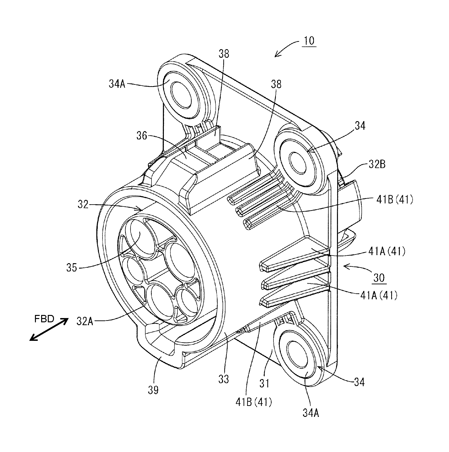
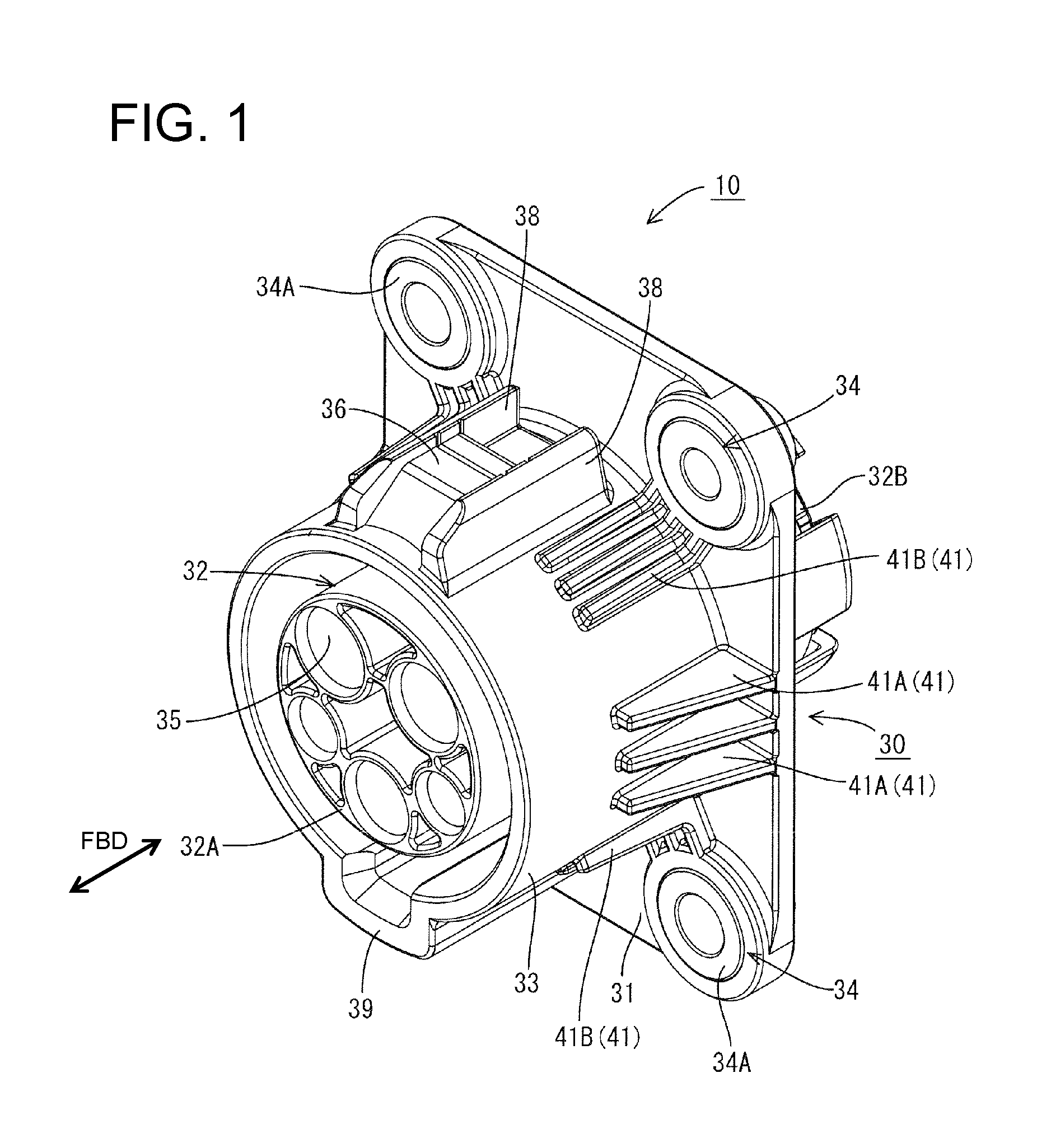
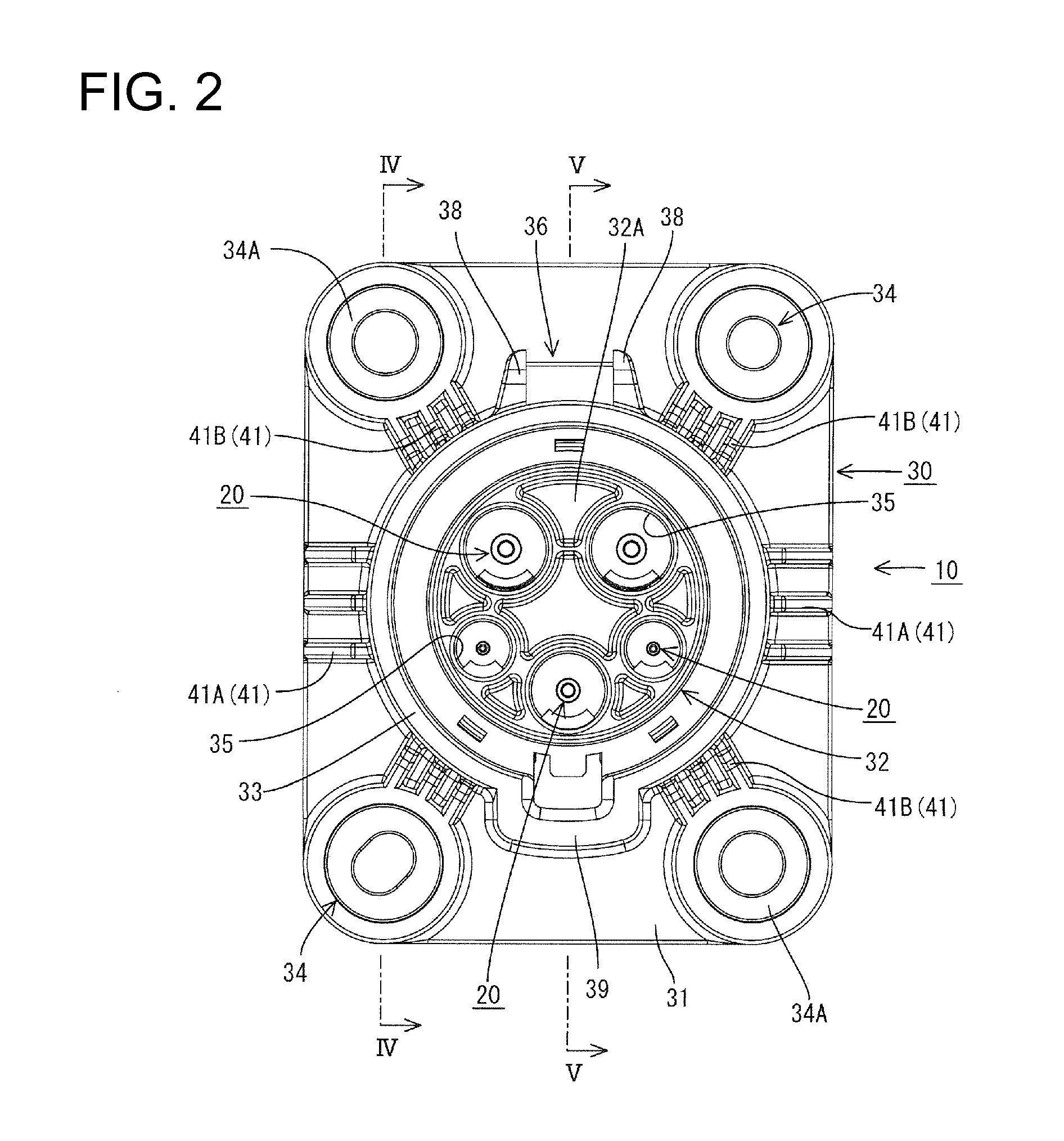
[0027]A vehicle-side connector 10 of this embodiment is shown in FIGS. 1 and 2, and includes vehicle-side terminal fittings 20 and a housing 30 made e.g. of synthetic resin. The vehicle-side connector 10 is to be fixed to a vehicle B, as shown in FIG. 5, and an unillustrated charging connector is connectable to the housing 30 from the front.

[0028]Each vehicle-side terminal fitting 20 includes a terminal connecting portion 21 in the form of a round pin and a wire connecting portion 22 to be connected to an unillustrated wire, as shown in FIG. 5. The terminal connecting portion 21 is to be connected electrically conductively to a charging-side terminal fitting in the charging connector when the charging connector is connected to the housing 30.

[0029]The housing 30 includes a mounting piece 31 in the form of a substantially rectangular or polygonal flat plate, as shown in FIGS. 1 and 5. A substantially tubular terminal accommodating portion 32 penetrates the mounting piece 31 in forwar...


PUM


Abstract

A vehicle-side connector (10) to be connected to a charging connector in charging a battery of a vehicle includes a receptacle (33) which is made of synthetic resin and to be connected to the charging connector, a mounting piece (31) which is made of synthetic resin and integrally provided to the outer peripheral surface of the receptacle (33), collars (34) each including a flange (34A) engageable with the mounting piece (31) in a connecting direction, and reinforcing portions (41) integrally connected to the mounting piece (31) and the receptacle (33).

Description

BACKGROUND OF THE INVENTION[0001]1. Field of the Invention[0002]The invention relates to a vehicle-side connector to be connected to a charging connector during or for charging.[0003]2. Description of the Related Art[0004]Japanese Unexamined Patent Publication No. 2010-166756 discloses a vehicle-side connector to be mounted on a vehicle body of a hybrid vehicle or an electric vehicle. The vehicle-side connector includes a connecting portion made of synthetic resin and to be connected to a charging connector. A mounting piece made of synthetic resin projects integrally from the outer surface of the connecting portion and collars made of metal are press-fit to this mounting piece. The vehicle-side connector is mounted and fixed to the vehicle body by inserting fixing bolts into the collars and tightening them into the vehicle body.[0005]A seal, such as a surface seal, is mounted between the mounting piece and the vehicle to prevent the water from entering the vehicle interior through ...

Claims


Application Information

Patent Timeline
Patent Type & Authority Patents(United States)
IPC IPC(8): H01R12/00
CPCH01R2201/26H01R13/50B29C45/14639H01R13/748H01R43/18
Inventor OSAWA, KIYOSHI
Owner SUMITOMO WIRING SYST LTD
Why Eureka
Try Eureka