Direct-push connecting pipe joint

A technology for connecting pipes and horn holes, applied in the field of pipe joints, can solve the problems of waste of pipes, high cost, disconnection of connecting pipes, etc., and achieve the effects of easy production, storage and transportation, reducing difficulty and cost, and avoiding truncation and damage.

Active Publication Date: 2014-05-07
张颂文
View PDF6 Cites 11 Cited by
  • Summary
  • Abstract
  • Description
  • Claims
  • Application Information

AI Technical Summary

Problems solved by technology

When the connected pipe is pushed straight into the through hole of the joint body, the elastic snap ring will be wedged tightly in the annular snap ring groove of the connected pipe; when the connected pipe is pulled out, the elastic snap ring acts as a The locking part will be wedged tightly by the small mouth of the horn hole, so that the connected pipe cannot be pulled out
[0004] It can be seen that the function of the groove of the ring snap ring is particularly important. If the depth of the groove of the ring snap ring is too large, the elastic opening snap ring will be firmly wedged and difficult to take out, and even the pipe wall of the connected pipe will be pressed out by a ring pressure. If the depth of the groove of the ring snap ring is too small, the elastic opening snap ring will easily slip off and slip, which will not be able to wedge the connected pipe, resulting in the connected pipe being pulled out at will.
[0005] However, the pipe wall of the current general connected pipe is usually smooth. If the above-mentioned direct push connection pipe joint is adopted, the connected pipe must be processed to form a suitable annular snap ring groove, which not only increases installation process, the processing is difficult and the cost is high, and it is easy to cut off the connected pipe when opening the ring snap ring groove, resulting in waste of pipe materials

Method used


Image

  • Direct-push connecting pipe joint
  • Direct-push connecting pipe joint
  • Direct-push connecting pipe joint

Examples


Embodiment Construction

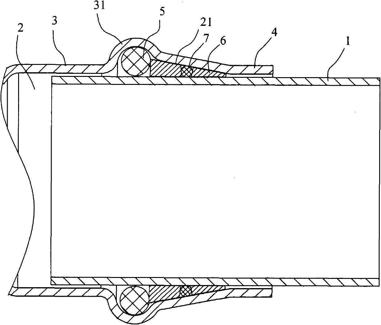
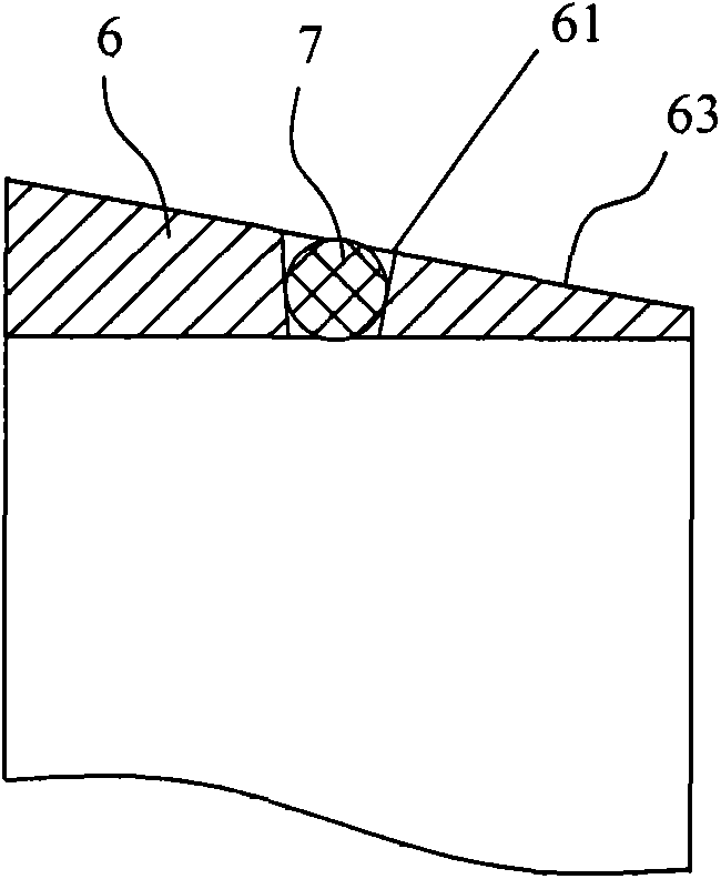
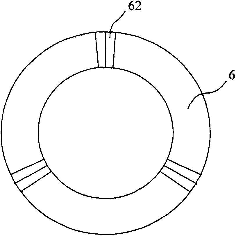
[0030] Such as figure 1 The shown direct push connecting pipe joint includes a joint body 3 having a through hole 2 for insertion of the connected pipe 1, a horn hole 21 is provided at the end of the through hole 2, and the big mouth of the horn hole 21 faces inward, and the horn hole The small mouth of 21 faces outward, and the joint body 3 wall between the small mouth of the horn hole 21 and the port of the through hole 2 is a sealing section 4, and a sealing rubber ring 5 is arranged in the big mouth of the horn hole 21, and a sealing rubber ring 5 is arranged in the small mouth of the horn hole 21. With locking parts. The locking part includes a support ring 6 and at least three balls 7 for being sleeved on the connected pipe 1. The inner end of the support ring 6 is pressed against the sealing rubber ring 5, and each ball 7 is rollingly installed on the support ring 6 Inside, and each ball 7 protrudes from the inner and outer peripheral surfaces of the supporting ring 6 ...


PUM


Abstract

The invention discloses a direct-push connecting pipe joint. The direct-push connecting pipe joint comprises a joint body provided with a through hole used for insertion of a connected pipe, wherein a bellmouth orifice is formed in the end part of the through hole; the big mouth of the bellmouth orifice faces inwards and the small mouth of the bellmouth orifice faces outwards; the wall body of the joint body between the small mouth of the bellmouth orifice and the end part of the through hole is a sealing section; an O-ring seal is internally arranged in the big mouth of the bellmouth orifice; a locking component is internally arranged in the small mouth of the bellmouth orifice; the locking component comprises a bearing ring used for being sleeved upon the connected pipe and at least three roll balls; the inner side end of the bearing ring extrudes the O-ring seal; each roll ball is mounted inside the bearing ring in a rolling manner; the inner circumferential surface and the outer circumferential surface of the bearing ring bulge each roll ball. The direct-push connecting pipe joint provided by the invention can reduce the difficulty of installation and connection and the cost, and the connected pipe can be firmly locked.

Description

technical field [0001] The invention relates to a pipe joint, in particular to a direct push connection pipe joint. Background technique [0002] A pipe joint refers to a connecting piece that connects two sections of pipes. At present, most pipe joints are connected by threads or elastic split rings. These connection methods are relatively complicated and inefficient. [0003] Chinese invention patent discloses a direct push connection pipe joint (application number is 200910040489.4), which includes a joint body, a horn hole is arranged in the through hole of the joint body, and a sealing rubber ring and an elastic opening snap ring are arranged in the horn hole . When the connected pipe is pushed straight into the through hole of the joint body, the elastic snap ring will be wedged tightly in the annular snap ring groove of the connected pipe; when the connected pipe is pulled out, the elastic snap ring acts as a The locking part will be wedged tightly by the small mou...

Claims


Application Information

Patent Timeline
Patent Type & Authority Applications(China)
IPC IPC(8): F16L37/23
CPCF16L37/23
Inventor 张颂文
Owner 张颂文
Why Eureka
Try Eureka