Portable Slow Cooker

a slow cooker and portability technology, applied in the field of slow cookers, can solve the problems of affecting the use of users, affecting the operation of the slow cooker, and the lid tends to slide off, so as to prevent the soup from spilling out, facilitate movement, and facilitate operation

Active Publication Date: 2013-04-25
MIDEA GRP CO LTD
View PDF36 Cites 10 Cited by
  • Summary
  • Abstract
  • Description
  • Claims
  • Application Information

AI Technical Summary

Benefits of technology

[0014]To prevent the handle from sliding down to the lowest position to be locked under the gravity force, a restoring mechanism for supporting the handle is provided within the handle box. When the handle is unlocked at the lowest position, it can automatically leave the lowest position, with no need of manual operation, thus it is more easily to operate.
[0015]For easy movement with a single hand, the said handle has an inverted U shape, with two lower ends inserted into the handle boxes, to slide upward and downward. The crossbar of the handle is pressed against the lid when the handle is placed at the lowest position. The inverted-U shaped handle is not only convenient for movement with a single hand, but also connected to the two sides of the cooking body, and therefore is uniformly forced to move smoothly to prevent the soup from spilling out.
[0016]Typically the lid of the slow cooker is provided with a grip, and preferably, the crossbar of the handle is pressed against the grip of the lid when the handle is at the lowest position. In this way, the grip is pressed by the crossbar, with no direct connection to the lid, so that heat will rarely be transferred to the handle during cooking to prevent high temperature of the handle, and thus is convenient for users.
[0017]The handle can be locked at the lowest position via various ways. Two types of structure are provided in the present invention. The first type provides a handle with a lock catch at each of the lower ends, and each of the handle boxes is provided with a flexible pressing buckle, which is match with the said lack catch to lock the handle at the lowest position. Specifically, the said handle box includes a box base, a box lid, a positioning buckle and a trigger, wherein the restoring mechanism is a spring installed within the handle box, which is disposed on the box base. The trigger is rotatably connected to the box lid, and the positioning buckle is rotatably connected to the trigger. A slider that slides within the box base is rotatably connected to the lower end of the handle. This kind of structure is simplified and convenient for users, with strengthened locking force.
[0018]Another type provides a handle box with a two-stage positioning mechanism, in correspondence with the highest position and lowest position of the handle respectively. Specifically, each of the handle box includes a box base, a box lid, a positioning buckle, a resetting spring sheet and a trigger. The positioning buckle, the resetting spring sheet and the trigger are installed between the box lid and the box base. The restoring mechanism is a spring installed within the handle box. At one side of the positioning buckle is provided with a two-stage latching position, i.e., a higher one and a lower one. At the other side of the positioning buckle is provided with the resetting spring sheet supporting the positioning buckle. The positioning buckle is pushed by the trigger to press against the resetting spring sheet. A projecting rotate shaft, of which the end is provided with a position-limiting projection, is provided to the lower end of the handle to match with the two stage latching positions. For this kind of structure, the locking force is strengthened. It can be unlocked by pushing the trigger, and thus is convenient for users. Besides, no metal components as what is used in the previous type are required, therefore the temperature during operation can be lowered and make it more safe to operate.
[0019]In a word, the handle and the locking device of the lid are delicately integrated as a whole, with simplified structure and strengthened locking force to prevent the soup from spilling out during operation. It is convenient to remove the lid and the liner container and move with a single hand. It requires no further manufacture of the locking component on the lid, and thus is more easily to manufacture, suitable for lid made of any kind of materials, e.g., glass or ceramics. The locking mechanism and the unlocking mechanism are both disposed on the cooking body of the slow cooker, with little heat transferring, protecting the users from being burned during operation, owning to the high efficiency in decreasing the temperatures of these mechanisms. Compared with the prior arts, it is creative with substantive characteristics and obvious progress.

Problems solved by technology

The lid is typically not securely engaged with the container.
The lid tends to slide off during movement because there is no secure connection between the liner container and the lid.
Furthermore, the shaking caused by the movement can possibly cause spillage of the liquid content in the container, and thus may burn the user.
However, this design has too many parts, resulting in high cost and difficulty of assembly.
Moreover, the latch is subject to large area of friction, causing non-smooth operation.
Further, the steel bead is positioned by the elastic force of the spring which may deteriorate during long term use, resulting in high possibility of latch release.
This will lead to additional cost and more complicated manufacturing process for mounting such a catch, particularly on a glass lid as predominately used in slow cookers.
Slow cooker with this structure requires to be operated with two hands simultaneously, and is not able to be moved with a single hand.

Method used


Image

  • Portable Slow Cooker
  • Portable Slow Cooker
  • Portable Slow Cooker

Examples


embodiment 1

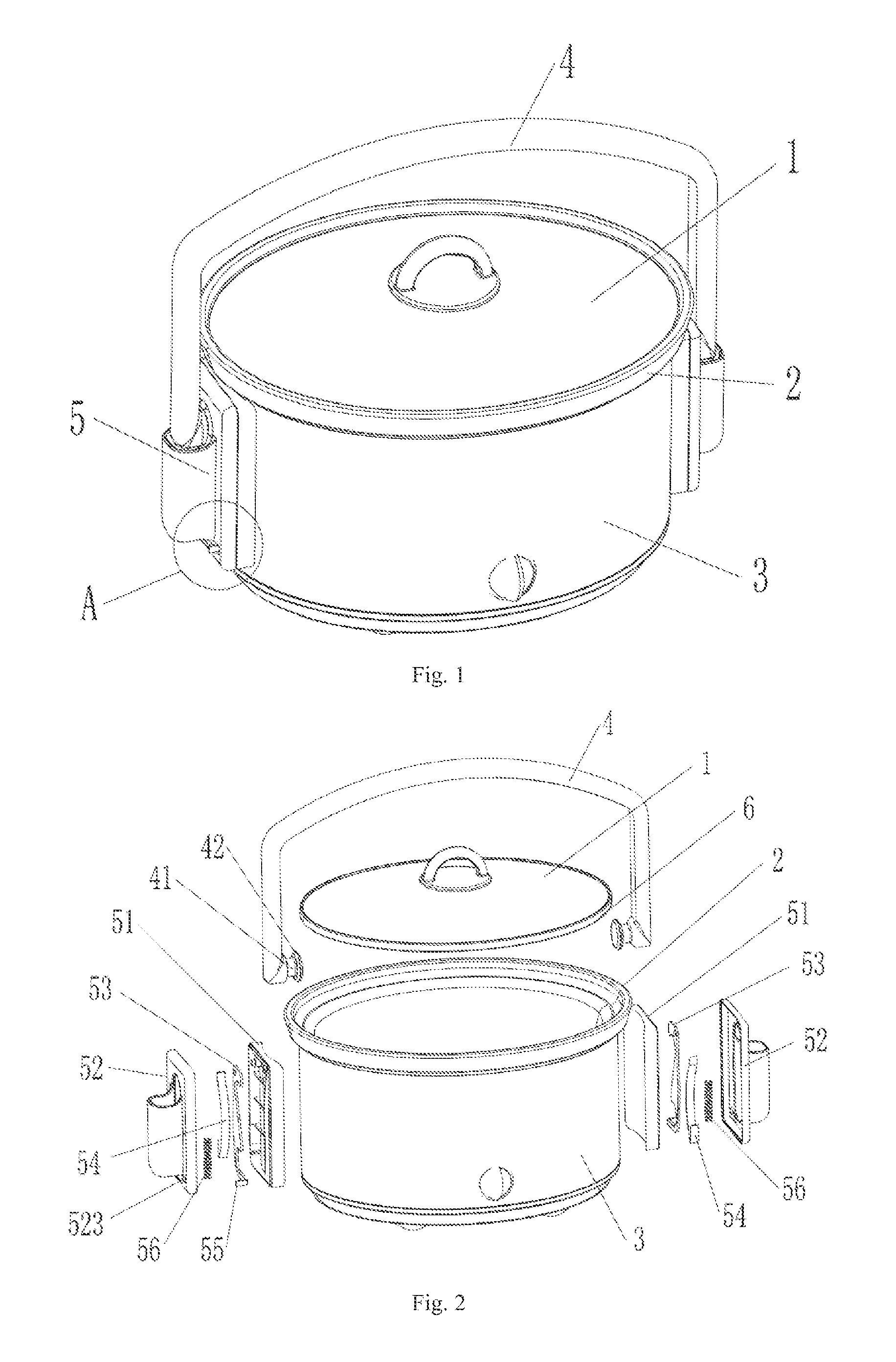
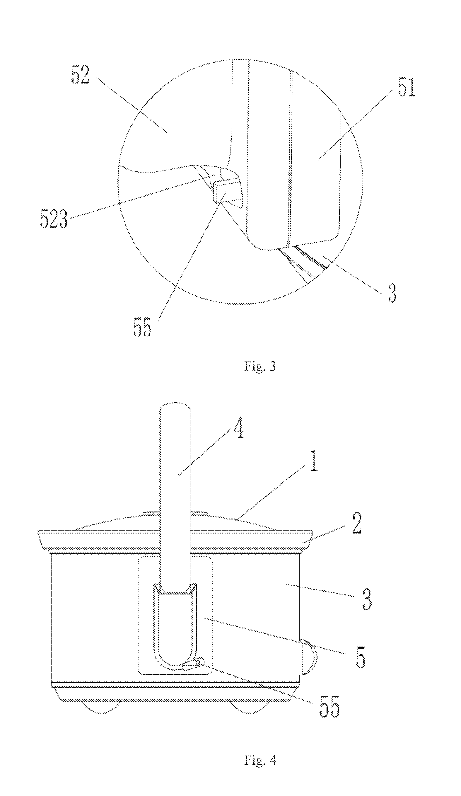
[0045]The portable slow cooker in this embodiment as show in FIGS. 1 to 14 includes a cooking body 3, a liner container 2 disposed within the cooking body 3, a lid 1 disposed on the liner container 2 covering the opening end of the liner container 2, a handle 4, a handle box 5 fixed on the two end side surface of the cooking body 3, and a sealing ring 6 disposed around the outer rim of the lid 1, and Within the handle box 5 is provided with a handling position and a fixed position. The handle 4 has two lower ends that can remove upward and downward to be fixed in the handle box 5, and selectively be fixed at the handling position or fixed position of the handle box 5, has an inverted U shape, and is disposed over the lid 1. When the two ends of the handle 4 are fixed at the fixed position of the handle box 5, the handle press tightly on the grip of the lid 1, making the lid 1, the sealing ring 6 and the liner container 2 closely joint together, insuring food within the liner contain...

embodiment 2

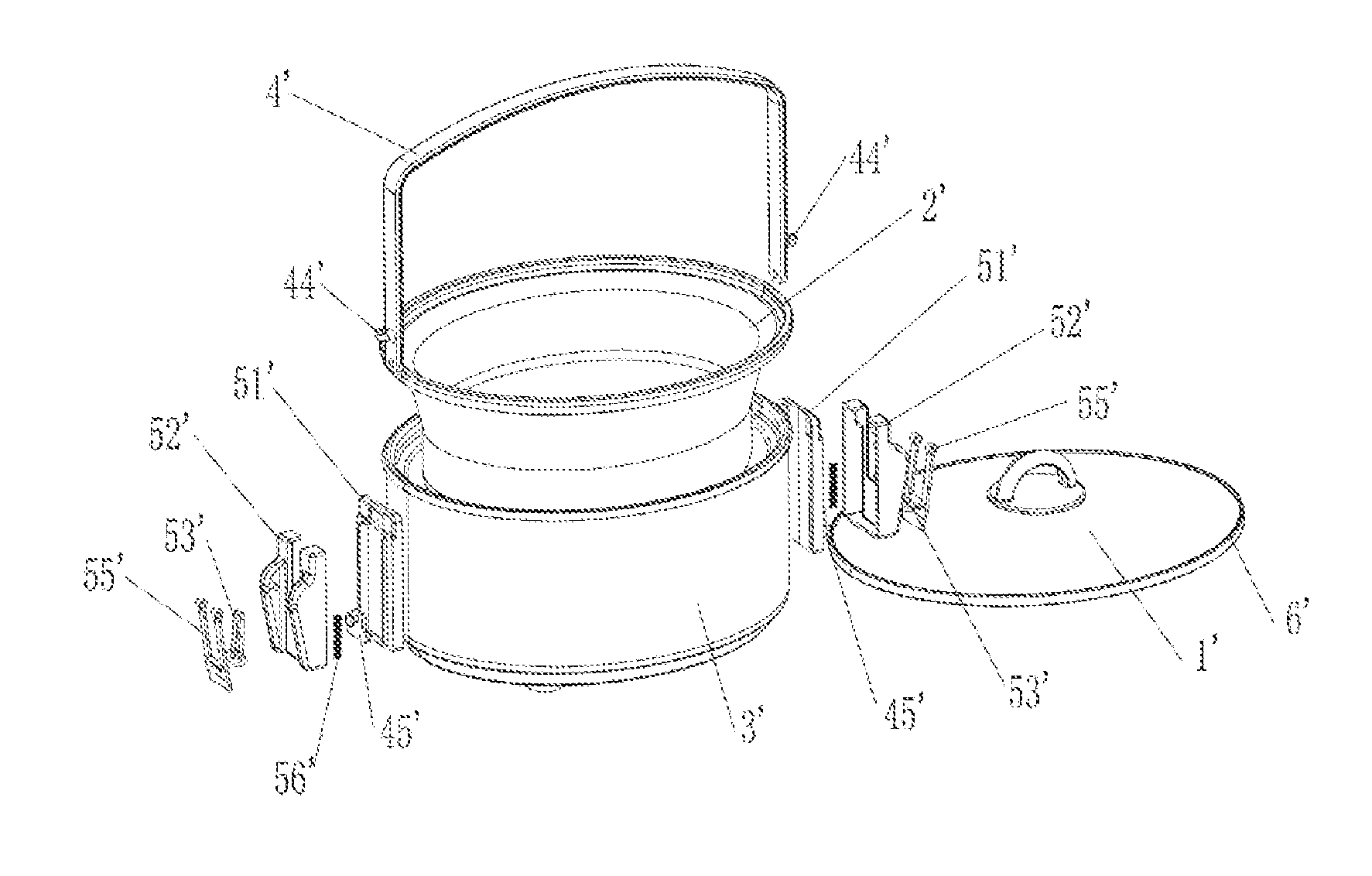
[0059]As shown in FIGS. 15 to 24, the slow cooker in the present embodiment includes a cooking body 3′, an liner container 2′ disposed within the cooking body 3′, an lid 1′ disposed on the liner container 2′ covering the opening of the liner container 2′, a handle 4′, a handle box 5′ fixed on the two end side surface of the cooking body 3′, and a sealing ring 6′ disposed around the outer rim of the lid 1′.

[0060]Different from the embodiment 1, the handle box 5′ in the present embodiment includes a box base 51′, a box lid 52′, a positioning buckle 53′, a trigger 55′, and a spring 56″. The box base 51′ is fixed to the cooking body 3′ via fasteners, e.g., screws. The outside wall of the box base 51′ is closely next to the side wall of the cooking body 3′. The inner side wall of the box base 51′ is provided with two parallel locating wings 513′ in the vertical direction. A skid 514′ for the upward and downward movement of the handle 4′ is formed between the two locating wings 513′. A fi...


PUM


Abstract

A new portable slow cooker capable of engaging a lid and a liner container can is provided to prevent the soup from spilling out. The structure of the present invention comprises a cooking body, a liner container, a lid and a handle, wherein the liner container is disposed within the cooking body, and the lid is disposed on the opening of the liner container. The handle is spanned over the lid and has, lower ends in vertically slidable cooperation with handle boxes disposed at aside surface of the cooking body. The handle is locked by the handle boxes when slides to an lowest position, so as to press the lid to form a sealing engagement with the liner container. As long as the handle is pushed to the lowest position, being locked, the lid and the liner. container can be engaged to prevent the soup from spilling out.

Description

CROSS-REFERENCE TO RELATED APPLICATION[0001]The present application claims benefit from Chinese utility model application no. 201120410661.3 filed on Oct. 25, 2011 by Midea Group Co., Ltd. The entire disclosure of the application is hereby incorporated herein by reference.FIELD OF THE INVENTION[0002]The present invention relates to a slow cooker and, in particular, to a portable slow cooker having a multi-functional handle and capable of preventing spillage of cooking content such as soup.BACKGROUND OF THE INVENTION[0003]Conventional slow cooker comprises a liner container and a lid disposed on the top rim of the container. The lid is typically not securely engaged with the container. The user is likely to move the cooker or the liner container containing food after the food is well cooked. The lid tends to slide off during movement because there is no secure connection between the liner container and the lid. Furthermore, the shaking caused by the movement can possibly cause spilla...

Claims


Application Information

Patent Timeline
Patent Type & Authority Applications(United States)
IPC IPC(8): A47J36/10
CPCA47J36/10
Inventor CHEN, PINGTAOWU, JINSHUI
Owner MIDEA GRP CO LTD
Why Eureka
Try Eureka