Electrical connector with latch mechanism

a technology of latch mechanism and electric connector, which is applied in the direction of electrical apparatus, connection, coupling device connection, etc., can solve the problems of occupying additional space and frequent electrical interruption, and achieves convenient and reliable connection, convenient use, and convenient use.

Inactive Publication Date: 2006-12-05
CHENG UEI PRECISION IND CO LTD
View PDF8 Cites 11 Cited by
  • Summary
  • Abstract
  • Description
  • Claims
  • Application Information

AI Technical Summary

Benefits of technology

[0008]In the electrical connector mentioned-above, the latch mechanism is assembled in inner space of the insulating housing. Consequently, the electrical connector with latch mechanism of the present invention can make the most of the inner space to achieve a compact width. Furthermore, the cantilevers and the flexible slices increase the latch force to make the hooks latch the mating connector, therefore a reliable connection between the present electrical connector and the mating connector is achieved.

Problems solved by technology

A reliable connection between a pair of mated electrical connectors is crucial to the system; otherwise electrical interruption may be frequently caused.
However, the latch mechanisms mentioned above are arranged on two opposite sides of the electrical connector, which occupy additional space.

Method used


Image

  • Electrical connector with latch mechanism
  • Electrical connector with latch mechanism
  • Electrical connector with latch mechanism

Examples


Embodiment Construction

[0014]In order to illustrate the present invention particularly, including technology, structure trait, aims and efficiency, a detailed explanation of a preferred embodiment of the present invention will be given thereinafter, with reference to the attached drawings, for better understanding thereof to those skilled in the art.

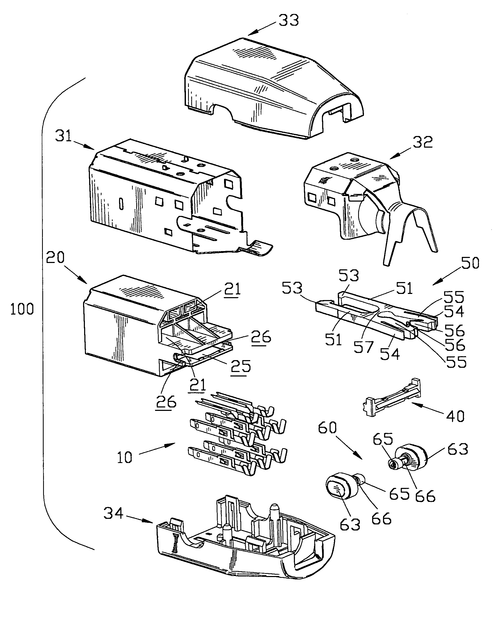
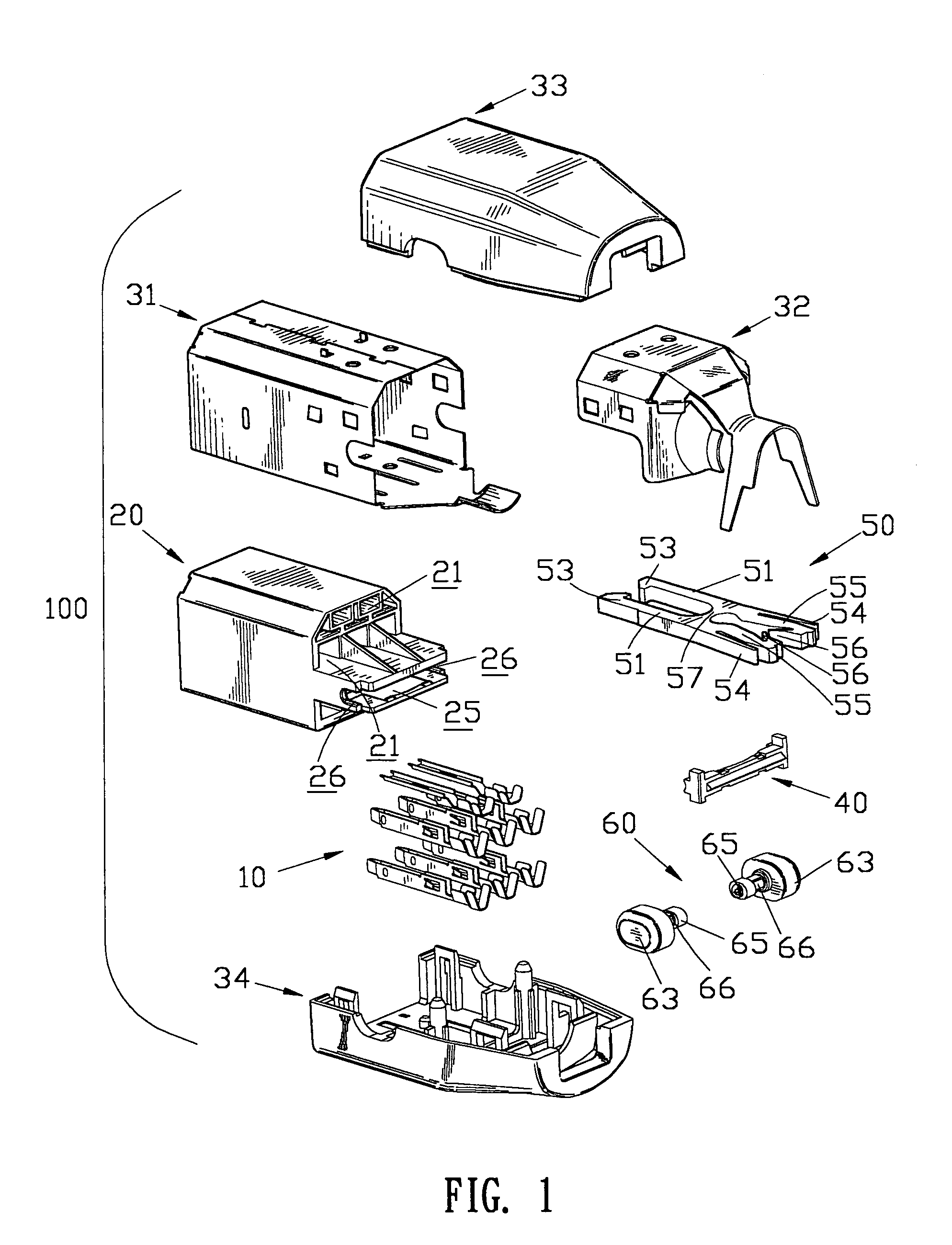
[0015]Referring to FIG. 1, an electrical connector 100 in accordance with the present invention comprises an insulating housing 20, a plurality of contacts 10 and a latch mechanism 50 received in the insulating housing 20, a primary metal shield 31 and a second metal shield 32 encircling the insulating housing 20, and an upper dielectric cover 33 and a lower dielectric cover 34 buckling the insulating housing 20.

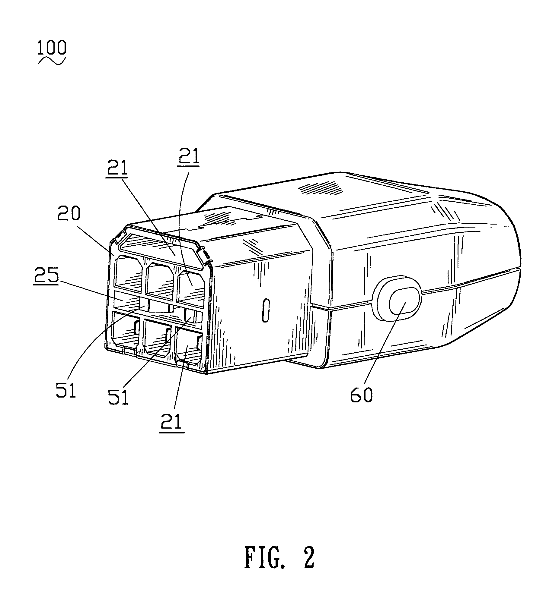
[0016]Referring to FIG. 2 in conjunction with FIG. 1, the insulating housing 20 defines a plurality of contact receiving channels 21 and a passageway 25 therein, which extend through the insulating housing 20 front to rear. The contact receiving channe...


PUM


Abstract

An electrical connector with latch mechanism includes an insulating housing having at least two rows of contact receiving channels and a passageway defined between the two rows of contact receiving channels, a plurality of contacts received in the contact receiving channels, and a latch mechanism mounted in the passageway including a pair of latch arms and a flexible beam flexibly connecting the latch arms. The pair of latch arms has a pair of hooks and a pair of force receiving portions forming a pair of cantilevers at outer sides thereof and a pair of flexible slices at inner sides thereof extending inwardly toward each other. During the force receiving portions are exerted to make the hooks latch a mating electrical connector, besides the flexible beam, the cantilevers and the flexible slices are deformed to cumulate resilience which produces an increased latch force when the force receiving portions are released.

Description

BACKGROUND OF THE INVENTION[0001]1. Field of the Invention[0002]The present invention generally relates to an electrical connector, and more specifically to an electrical connector having a latch mechanism for connecting and releasably locking the electrical connector to a mating electrical connector.[0003]2. The Related Art[0004]Electrical connectors are widely applied in electrical connection systems. A reliable connection between a pair of mated electrical connectors is crucial to the system; otherwise electrical interruption may be frequently caused. To obtain a reliable connection, more and more connectors are designed to have a latch mechanism.[0005]U.S. Pat. No. 5,154,629 issued on Oct. 13 in 1992 describes an electrical connector with a pair of latch mechanisms. The electrical connector disclosed in the patent includes a cable coupled to an electrical connector housing, which is enclosed by a molded outer housing. The outer housing has a pair of side cavities pivotally recei...

Claims


Application Information

Patent Timeline
Patent Type & Authority Patents(United States)
IPC IPC(8): H01R13/627
CPCH01R13/6275H01R9/032H01R13/65912
Inventor HUANG, MAO-JUNGYIN, TE-HUNGCHEN, PING-CHIH
Owner CHENG UEI PRECISION IND CO LTD
Why Eureka
Try Eureka