Hydro-magnetic linear actuator

An actuator and fluid bearing technology, applied in the field of actuators including linear motors, can solve the problems of equipment cost and size increase, indistinguishable, reduce the peak frequency of the actuator, etc., achieve low mechanical friction and wear, low The effect of inertia

Inactive Publication Date: 2019-10-11
LIBERTINE FPE
View PDF9 Cites 0 Cited by
  • Summary
  • Abstract
  • Description
  • Claims
  • Application Information

AI Technical Summary

Problems solved by technology

[0007] Second, servohydraulic systems require expensive and specialized infrastructure within the test facility, which can be extremely bulky, and must still be located relatively close to the hydraulic actuators to limit the inertia of the oil moving within the system
Additionally, the infrastructure requires professional expertise to operate and maintain
[0008] Third, servo hydraulics are large consumers of electricity, making their operation expensive and contributing to the carbon footprint of vehicle development and manufacturing
[0009] Fourth, servohydraulic systems can be extremely noisy, making it difficult to distinguish between noise due to the test object's response and the associated noise of the test actuator system itself
This extra inertia reduces the peak frequency the actuator can achieve for a given displacement
[0015] Second, the use of compliant members such as airbags or mechanical springs introduces the potential for unwanted resonances in the test actuator system, compromising the integrity of the input function applied to the test object
[0016] Third, due to the need to couple discrete spring and motor assemblies within each actuator test frame, the arrangement taught by US7401520 requires unnecessary structural complexity, resulting in increased cost and size of the overall apparatus
This friction will affect the net force applied to the test object and may also cause wear and shortened life of the actuator
[0021] Third, the arrangement taught by US8844345 requires unnecessary structural complexity due to the need to couple motors, pneumatic cylinders, movable members and mounts for test objects within each actuator test frame, resulting in overall equipment cost and size increase

Method used


Image

  • Hydro-magnetic linear actuator
  • Hydro-magnetic linear actuator
  • Hydro-magnetic linear actuator

Examples


Embodiment Construction

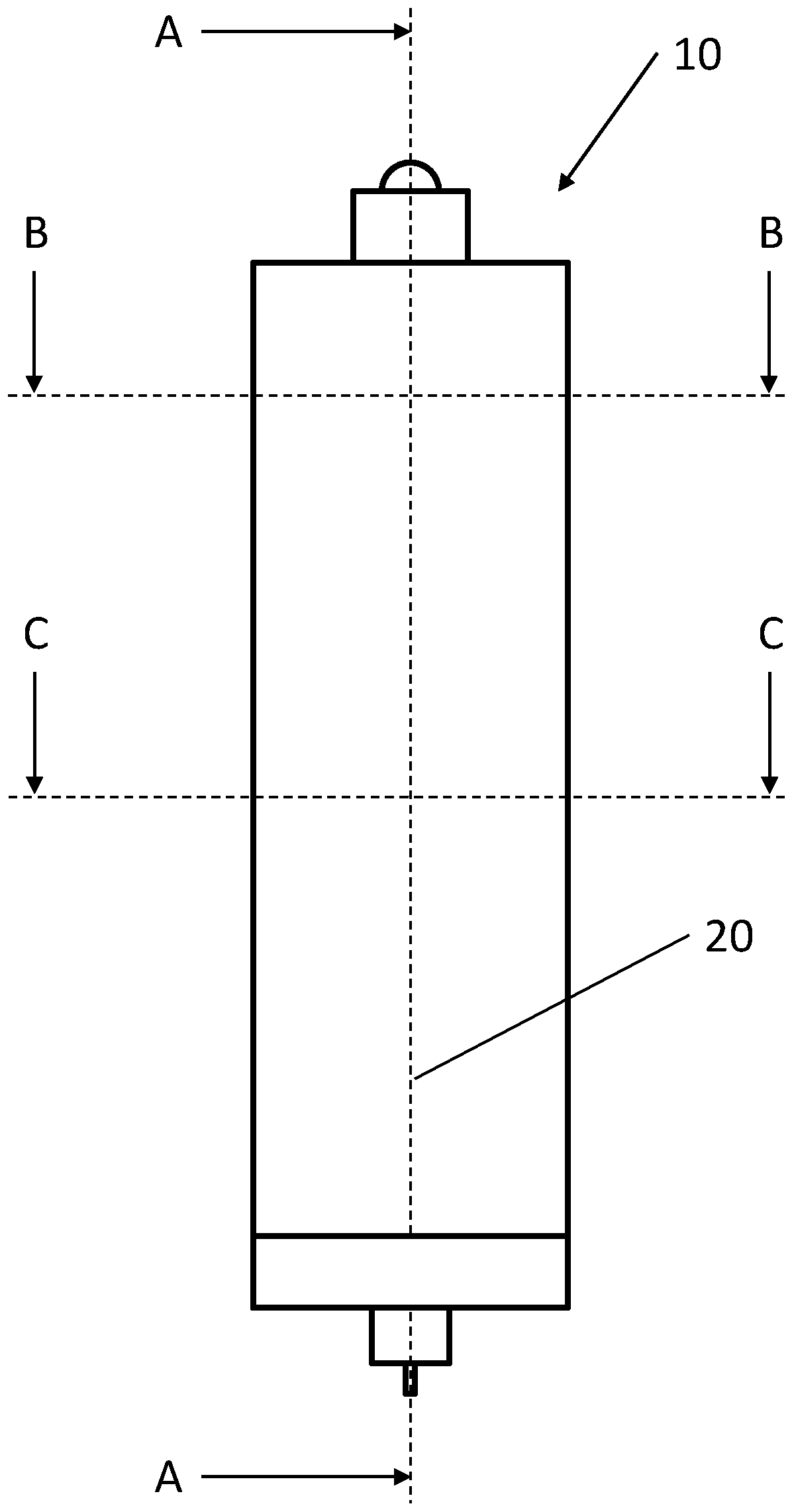
[0060] figure 1 is an external view of the first actuator 10 with an axis of motion 20 along which a translating body (shown later) moves and several planar positions for the other cross-sectional views.

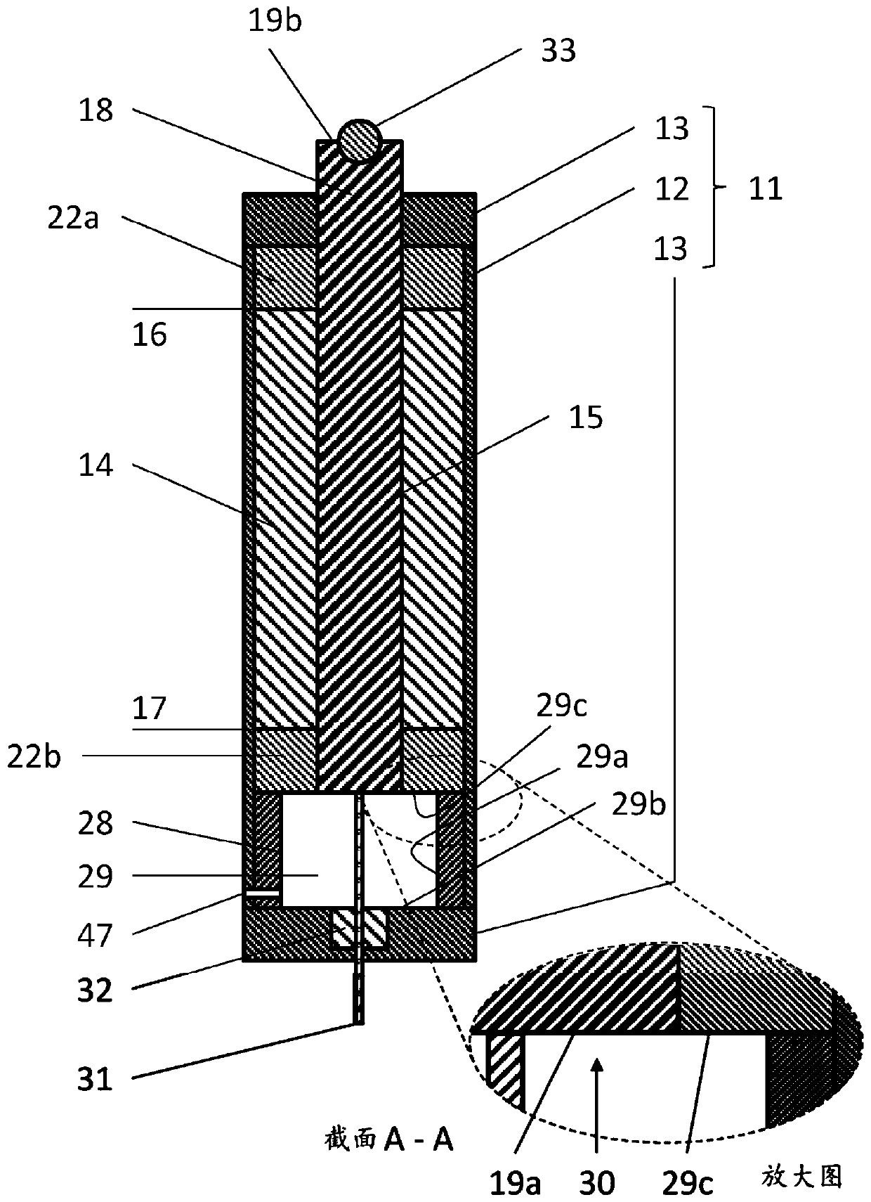
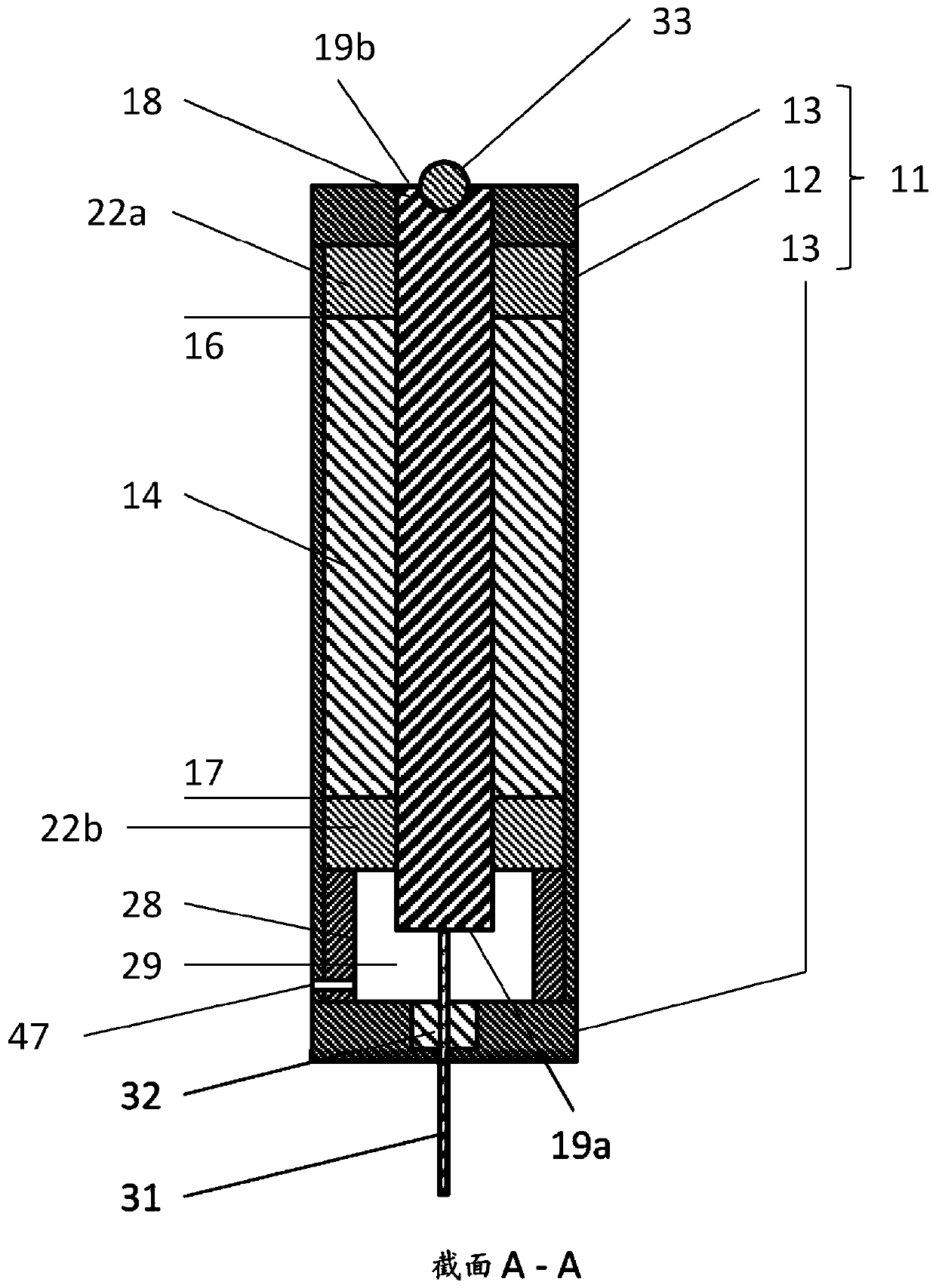
[0061] figure 2 The actuator 10 is shown with a housing body 11 . The housing body 11 is formed by a typically cylindrical wall 12 and by end walls 13 defining a hollow interior. Inside holds a stator 14 which is generally a tubular linear motor stator with a cylindrical bore 15 extending axially from one end 16 to the other 17 of the stator. The translation body 18 is axially movable relative to the stator 14 . There is an external magnetic circuit air gap 21 between the translation body and the stator (see Figure 5 ). In this example embodiment, the housing, and thus the stator, is rigidly held, and the translating body 18 moves within the stator 14 .

[0062] A pair of hydrodynamic bearings 22a and 22b are provided, the upper bearing 22a defining one end of the ac...


PUM


Abstract

An actuator comprising a linear electrical machine (LEM) having a stator with a stator bore and a translator axially movable within the stator bore and defining a magnetic circuit airgap therebetween,at least one fluid bearing journal formed on the translator, at least one fluid bearing providing a bearing gap adjacent the translator to allow the translator to move axially within the stator bore,a preload chamber for applying a preload force to the translator, wherein the preload chamber is defined by a side wall, a first end wall and a second end wall at least part of which is movable withthe translator, and wherein the bearing gap and the magnetic circuit airgap are coaxial.

Description

technical field [0001] The present invention relates to an actuator, and in particular to an actuator comprising a linear electric motor (LEM). Background technique [0002] Such actuators can be used in a variety of applications including, but not limited to: displacement and vibration test systems, manufacturing processes, and robotics. In displacement and vibration testing system applications, actuators can be used to apply cyclic forces or motion profiles to test objects. The test object can be a material sample, a discrete component, a sub-system assembly of a component, or a finished product. The purpose of such testing may be to determine the durability of the test object as a function of applied force or displacement. Alternatively, the test may seek to characterize the test object's response to an applied force or displacement function. [0003] This test actuator is widely used in the automotive industry for sub-assembly testing and finished product testing. Te...

Claims


Application Information

Patent Timeline
Patent Type & Authority Applications(China)
IPC IPC(8): H02K41/03H02K7/08H02K7/14F16C32/06G01M17/00
CPCG01M7/022G01M17/0074H02K41/031H02K7/083F16C32/06H02K7/14G01M7/02G01M7/04H02K5/167H02K7/08H02K41/03H02K11/215H02K5/1672F16C32/0607F16C32/0633F16C32/0629F16C32/0603
Inventor 爱德华·海恩斯塞缪尔·科克里尔
Owner LIBERTINE FPE
Why Eureka
Try Eureka