Hole punch

Inactive Publication Date: 2007-07-26
WORKTOOLS
View PDF7 Cites 7 Cited by
  • Summary
  • Abstract
  • Description
  • Claims
  • Application Information

AI Technical Summary

Benefits of technology

[0006] In one embodiment of the present invention hole punch, a handle pressing area is positioned opposite the handle hinge, with respect to the paper or sheet media slot. The hinge and pressing area are connected by a structure that extends under the paper slot, preferably at multiple or continuous locations along the paper slot. With multiple connections, or

Problems solved by technology

On the other hand, the great handle leng

Method used


Image

  • Hole punch
  • Hole punch
  • Hole punch

Examples


Embodiment Construction

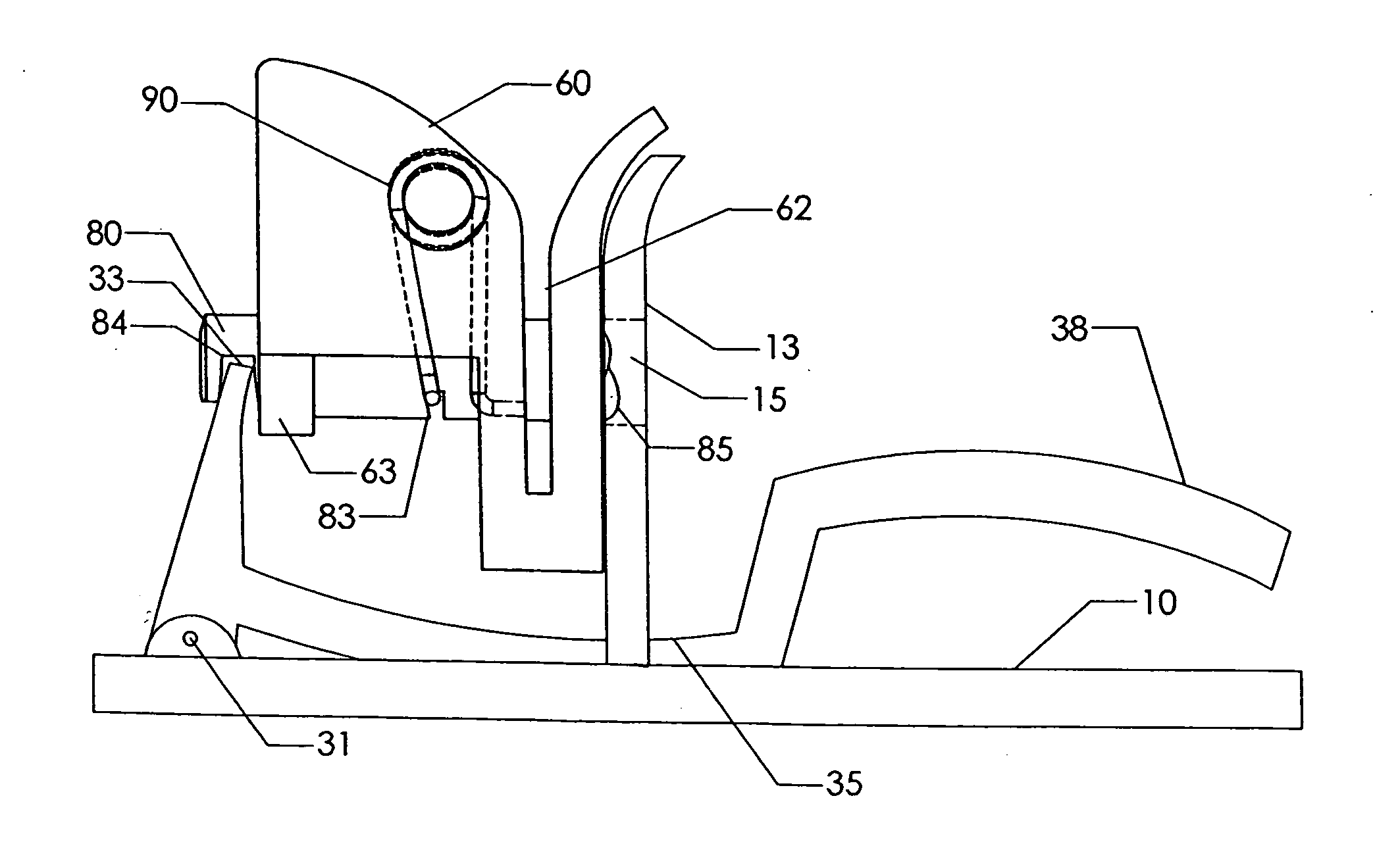
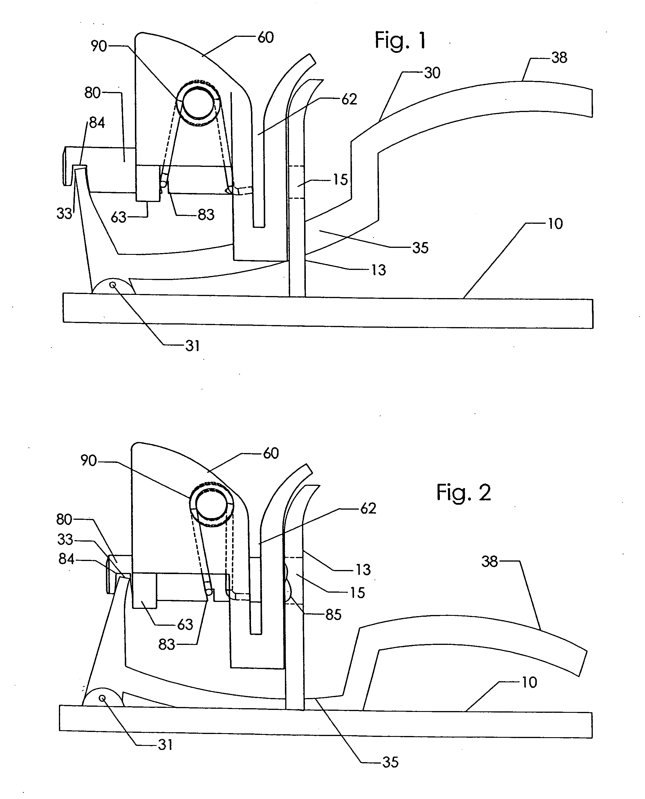
[0014]FIG. 1 is an end view of a preferred embodiment vertical entry hole punch. In the side elevational or profile view of FIGS. 1 and 2, base or support structure 10 includes a vertically extending rib 13. Rib 13 generally bisects support structure 10 into halves with a front end and a front half to the left in FIGS. 1-2 and a back half and a back end to the right. In the preferred embodiment shown, support structure 10 is fashioned into a large, flat, stable base.

[0015] Punch element 60 is supported on rib 13 with slot 62 extending preferably substantially vertically, or in various alternative embodiments at least partly vertically or at an angle from the vertical. The opening of slot 62 is preferably fairly straight upwards or angled upwards. Punch element 60 is preferably disposed in the front half of support structure 10 toward the front end (to the left in FIGS. 1-2). This balances the forces acting on the punching device since the downward actuating force applied by the use...


PUM

PropertyMeasurementUnit
Lengthaaaaaaaaaa
Areaaaaaaaaaaa
Heightaaaaaaaaaa

Abstract

A hole punch having one or more punch elements located above a base and having substantially upward opening slot(s) to hold a stack of papers or sheet media to be punched, and an L-shaped handle pivoting at the elbow in the L on the base, wherein one or more of the handle connectors extend in between, underneath, or along the outside of the punch elements. The punch elements include a horizontally translating punch pin having a notch hooked by an actuating end of the pivoting handle to produce the punching action.

Description

FIELD OF THE INVENTION [0001] The present invention relates to hole punches. More precisely, the present invention relates to a paper or sheet media hole punch with a sheet slot oriented in a generally vertical position. BACKGROUND OF THE INVENTION [0002] A hole punch device is used to create holes in one or more sheets of paper or other thin material. A punch pin is movable through the papers into a die hole to cut one or more holes in papers. Commonly the paper slot extends horizontally whereby the papers are inserted horizontally, for example parallel to a table top. In other designs the slot extends downward, for example toward a table top. The papers are moved down into the slot for punching. The pin moves horizontally. In a manually actuated punch a handle links through a support structure to the pin. The linkage should provide leverage so that a reasonable force upon the handle creates a large cutting force at the pin. [0003] In any punch device, it is desirable that the devi...

Claims


Application Information

Patent Timeline
IPC IPC(8): B26F1/14
CPCB26F1/36B26D5/10Y10T83/8809Y10T83/9428Y10T83/943
Inventor MARKS, JOEL S.
Owner WORKTOOLS
Why Eureka
Try Eureka