Circulating feeding mechanism

A feeding mechanism and circular conveying technology, which is applied in the direction of conveyors, conveyor objects, transportation and packaging, etc., can solve the problems of low working efficiency and slow product output speed of laminators

Pending Publication Date: 2020-01-03
SUZHOU HARMONTRONICS AUTOMATION TECH CO LTD
View PDF0 Cites 3 Cited by
  • Summary
  • Abstract
  • Description
  • Claims
  • Application Information

AI Technical Summary

Problems solved by technology

[0002] In the field of battery manufacturing, a single clamping device is generally used for the supply of pole pieces during the battery stacking process. The clamping device clamps and places the pole pieces at the stacking device and then repeats the operation again. However, during the cycle of the clamping device, the stacking The device is in an empty state, and this cooperation leads to problems such as low working efficiency of the stacker and slow product output.

Method used


Image

  • Circulating feeding mechanism
  • Circulating feeding mechanism
  • Circulating feeding mechanism

Examples


Embodiment Construction

[0013] In order to better understand the technical solution of the present invention, a preferred embodiment provided by the present invention will be described in detail below in conjunction with the accompanying drawings.

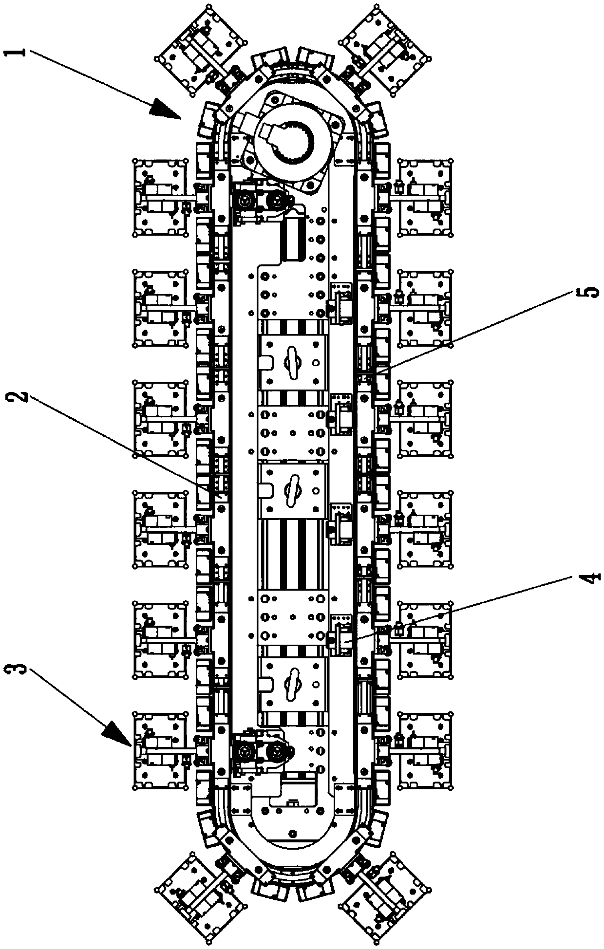
[0014] Such as figure 1 A circular feeding mechanism shown includes an annular conveying device 1, a pressing device 4, a workpiece pick-and-place device 3, a current collector 2, and an electrified track 5. The pressing device 4 is fixed on the annular conveying device 1, and the electrified track 5 Fixed on the circular conveying device 1, the circular conveying device 1 is connected with the workpiece pick-and-place device 3, the collector 2 is fixed on the workpiece pick-and-place device 3, and the collector 2 is connected with the electrified track 5.

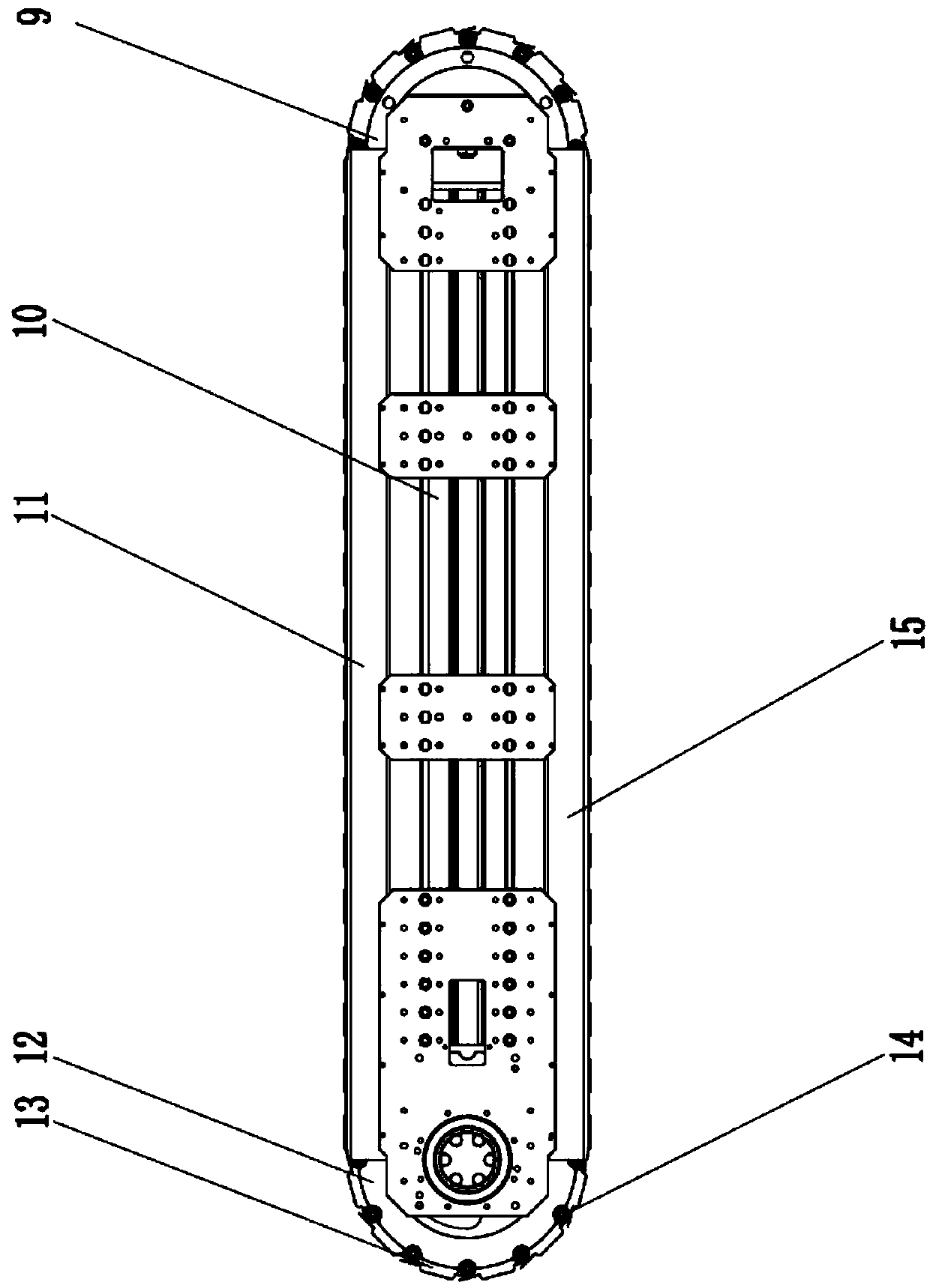
[0015] Such as image 3 The shown circular conveying device comprises a main board 10, a driving device 6, a driving wheel 12, a driven wheel 16, a first track 11, a second track 15, some chain link ...


PUM


Abstract

The invention relates to a circulating feeding mechanism which comprises an annular conveying device, a downward pressing device, a workpiece taking and placing device, a current collector and an electrified track. According to the circulating feeding mechanism, the working rhythm of a lamination stacking machine is improved, and the working efficiency is greatly improved.

Description

technical field [0001] The invention relates to a feeding mechanism, in particular to a circulating feeding mechanism. Background technique [0002] In the field of battery manufacturing, a single clamping device is generally used for the supply of pole pieces during the battery stacking process. The clamping device clamps and places the pole pieces at the stacking device and then repeats the operation again. However, during the cycle of the clamping device, the stacking The device is in an empty state, and this cooperation leads to problems such as low working efficiency of the laminating machine and slow product output speed. Contents of the invention [0003] The object of the present invention is to overcome the above-mentioned deficiencies in the prior art and provide a circular feeding mechanism. This mechanism adopts a plurality of workpiece pick-and-place devices for circular feeding. Sent to the stacking device, there is no vacant state during the whole stacking ...

Claims


Application Information

Patent Timeline
Patent Type & Authority Applications(China)
IPC IPC(8): B65G47/91B65G17/38
CPCB65G17/38B65G47/91
Inventor 崔九稳
Owner SUZHOU HARMONTRONICS AUTOMATION TECH CO LTD
Why Eureka
Try Eureka