Deployable hood device for stationary orbit remote sensing camera

A remote sensing camera and geostationary orbit technology, applied in the aerospace field, can solve problems such as the inability to place a fixed hood, the reduction of the signal-to-noise ratio of the optical system, and the reduction of camera imaging quality, and achieve high reliability, large driving force, and locking force big effect

Active Publication Date: 2018-01-19
CHANGCHUN INST OF OPTICS FINE MECHANICS & PHYSICS CHINESE ACAD OF SCI
View PDF7 Cites 10 Cited by
  • Summary
  • Abstract
  • Description
  • Claims
  • Application Information

AI Technical Summary

Problems solved by technology

[0002] At present, light shields are widely used in the field of space telescopes and earth remote sensing. The light shields that are conventionally used in space optical systems are no longer deployed. With the increase of optical aperture, this form of light shield is no longer suitable for large-aperture space. development of optical systems
At the same time, a remote sensing camera operating in geostationary orbit faces a special space environment, and the angle between it and the sunlight changes in a 24-hour cycle. On the one hand, the sunlight directly shining on the light inlet of the camera will introduce stray light, causing the irradiance of the image plane to decrease. , the signal-to-noise ratio of the optical system decreases; on the other hand, the introduced heat leads to the destruction of the internal thermal balance, which reduces the imaging quality of the camera. The fairing length of the launch rocket is limited, and the conventional fixed sunshade can no longer be placed inside the rocket. There is an urgent need for an expandable sunshade solution
[0003] To sum up, the expandable hood of remote sensing cameras has received more and more attention, but the related research is relatively lagging behind, and there is no application case of deploying the hood of remote sensing cameras in geostationary orbit.

Method used


Image

  • Deployable hood device for stationary orbit remote sensing camera
  • Deployable hood device for stationary orbit remote sensing camera
  • Deployable hood device for stationary orbit remote sensing camera

Examples


Embodiment Construction

[0013] The present invention will be described in further detail below in conjunction with the accompanying drawings and embodiments.

[0014] An expandable hood device for a remote sensing camera with a diameter of 3 meters in geostationary orbit includes:

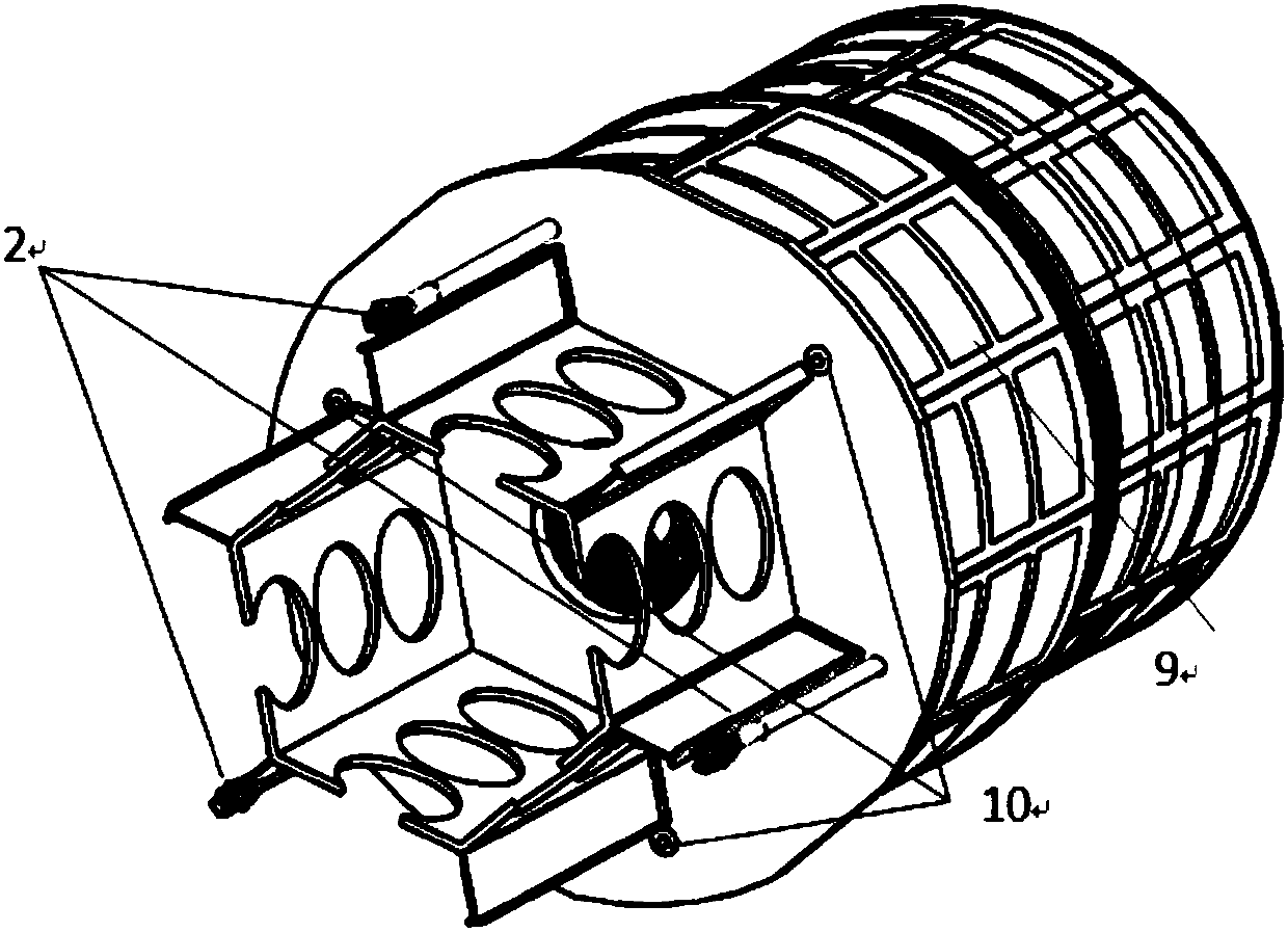
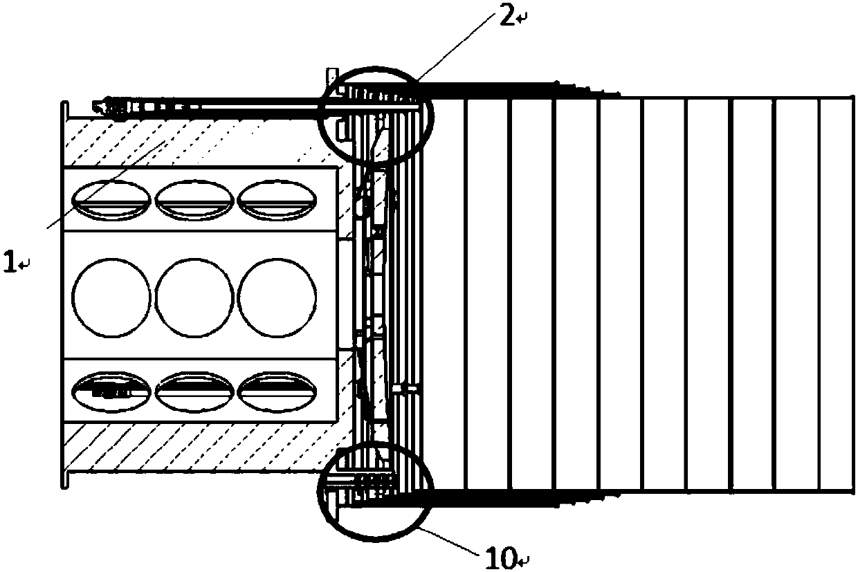
[0015] Optomechanical structure body 1, pull cord sleeve driving mechanism 2, multi-stage shading cylinder, shading cylinder heating plate 9 and locking mechanism 10. Such as figure 1 and figure 2 As shown, in this embodiment, the number of multi-stages is six.

[0016] The light-mechanical structure body 1 is fixed to the first-stage shading cylinder 3 in the multi-stage shading cylinder, and the multi-stage shading cylinder realizes the compressed state through the locking mechanism 10; Similarly, each level of sleeve is rigidly connected to the corresponding level of shading tube. When unlocking, the locking mechanism 10 is activated, and the multi-level shading tube is in a released state, and the multi-level slee...


PUM


Abstract

A deployable hood device for a stationary orbit remote sensing camera belongs to the spaceflight field. The device comprises an optical-mechanical structure body, a multistage hood cylinder, a lockingmechanism and a cord sleeve driving mechanism. The multistage hood cylinder is fixed with the optical-mechanical structure body and achieves the compressed state by the locking mechanism; the stagesof the core sleeve driving mechanism is the same as that of the multistage hood cylinder; the sleeve of each stage of the cord sleeve driving mechanism is in rigid connection with the corresponding stage of the hood cylinder of the multistage hood cylinder, and the multistage hood cylinder achieves multistage sleeve unfolding through the cord sleeve driving mechanism; a main mirror is arranged inthe first stage sleeve of the cord sleeve driving mechanism; and the circumference of each stage of the locking mechanism is uniformly distributed on the corresponding stage of the multi-stage hood cylinder. The compression ratio of the deployable hood device is high; the driving force of the cord sleeve driving mechanism is large and the synchronism is high; the structural rigidity of the whole device in the compressed state is high, and the whole device can bear the vibration impact load during the launching; and the reliability of the locking / unlocking is high, and the locking force is large.

Description

technical field [0001] The invention belongs to the aerospace field, and in particular relates to an expandable shading device for a remote sensing camera with a diameter of 3 meters in a geostationary orbit. Background technique [0002] At present, light shields are widely used in the field of space telescopes and earth remote sensing. The light shields that are conventionally used in space optical systems are no longer deployed. With the increase of optical aperture, this form of light shield is no longer suitable for large-aperture space. Development of optical systems. At the same time, a remote sensing camera operating in geostationary orbit faces a special space environment, and the angle between it and the sunlight changes in a 24-hour cycle. On the one hand, the sunlight directly shining on the light inlet of the camera will introduce stray light, causing the irradiance of the image plane to decrease. , the signal-to-noise ratio of the optical system decreases; on ...

Claims


Application Information

Patent Timeline
Patent Type & Authority Applications(China)
IPC IPC(8): G02B26/02G03B11/04
Inventor 曹乃亮董得义柴方茂鲍赫李志来
Owner CHANGCHUN INST OF OPTICS FINE MECHANICS & PHYSICS CHINESE ACAD OF SCI
Why Eureka
Try Eureka