Double-motor synchronous control device and method for silicon chip conveying manipulator

A synchronous control, manipulator technology, applied in the direction of speed adjustment of multiple motors, can solve the problems of arm asynchrony, arm end tray jitter, damage to silicon wafers, etc., to improve arm synchronization, avoid silicon wafer damage, and improve synchronization. sexual effect

Active Publication Date: 2012-07-04
SHENYANG SIASUN ROBOT & AUTOMATION
View PDF6 Cites 27 Cited by
  • Summary
  • Abstract
  • Description
  • Claims
  • Application Information

AI Technical Summary

Problems solved by technology

When the same control is applied to the two motors at the same time, the operation of the two arms will appear asynchronous, which will cause the pallet at the end of the arm to vibrate, and even slip and damage the silicon wafer

Method used


Image

  • Double-motor synchronous control device and method for silicon chip conveying manipulator
  • Double-motor synchronous control device and method for silicon chip conveying manipulator
  • Double-motor synchronous control device and method for silicon chip conveying manipulator

Examples


Embodiment Construction

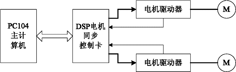
[0024] Such as figure 1 Shown, the present invention comprises main computer, DSP motor synchronous control card, motor driver and motor, wherein main computer is as host computer, and DSP motor synchronous control card is as slave, both carry out communication connection, two output ends of DSP motor synchronous control card Connect with two motor drivers respectively, the control output terminal of each motor driver is connected to the motor, and the motor speed information is sent to the DSP motor synchronous control card through the motor driver.

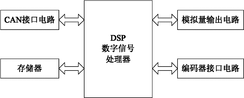
[0025] In this embodiment, the host computer adopts PC104, the host computer and the DSP motor synchronous control card communicate through the CAN bus, and the DSP motor synchronous control card acts as a slave. The host computer sends the position point of the trajectory planning to the DSP motor synchronous control card through the CAN bus every control cycle. The DSP motor synchronous control card is connected to the motor ...


PUM


Abstract

The invention relates to a double-motor synchronous control device and a double-motor synchronous control method for a silicon chip conveying manipulator. The method comprises the following steps of: planning and computing a trajectory by using a main computer to obtain expected positions of two motor output shafts; reading actual positions of the two motor output shafts through a coder interface circuit; performing proportion integration differentiation (PID) computation to obtain single-shaft position closed-loop control amount, and outputting the single-shaft position closed-loop control amount to a motor driver; according to the actual positions of the two motor output shafts, computing actual speeds of the two motor output shafts; according to the actual speeds of the two motor output shafts, respectively computing the speed difference and position difference of the two motor output shafts; inputting the speed difference and the position difference into a cross-coupling controller, and processing the speed difference and the position difference to obtain cross-coupling control amount; and adding the cross-coupling control amount to the single-shaft position closed-loop control amount, or subtracting the cross-coupling control amount from the single-shaft position closed-loop control amount, and then outputting a result to the motor driver, so that cross-coupling synchronous control of the two shafts can be realized. By the invention, arm synchronism can be improved in the operation process of the manipulator, the damage to silicon chips is avoided, the asynchronism of the manipulator can be compensated, and the synchronism is improved.

Description

technical field [0001] The invention relates to the control technology of a silicon wafer transport manipulator, in particular to a silicon wafer transport manipulator dual-motor synchronous control device and a method thereof. Background technique [0002] The silicon wafer transfer manipulator is a special robot used in the integrated circuit manufacturing industry for efficient transfer and positioning of silicon wafers between different process modules on the production line. The integrated circuit manufacturing industry is characterized by ultra-precision, ultra-clean environment and miniaturization. A slight vibration during the transfer of silicon wafers may cause damage to the silicon wafers. This poses a problem for the stability of the silicon wafer transfer robot during operation higher requirements. [0003] The frog-leg type vacuum manipulator that is currently widely used is driven by two motors to operate the two arms. Due to the influence of factors such as...

Claims


Application Information

Patent Timeline
Patent Type & Authority Applications(China)
IPC IPC(8): H02P5/50H02P5/52H02P5/56
Inventor 曲道奎王金涛宋吉来邹风山
Owner SHENYANG SIASUN ROBOT & AUTOMATION
Why Eureka
Try Eureka