Height adjustable table

a height adjustable and table technology, applied in the field of tables, can solve the problems of inability to conveniently adjust the counterbalance force, the solution fails to provide a safety mechanism for preventing the movement of the upper column, and the difficulty of a person raising and lowering in a controlled fashion

Inactive Publication Date: 2006-07-06
STEELCASE INC
View PDF99 Cites 65 Cited by
  • Summary
  • Abstract
  • Description
  • Claims
  • Application Information

AI Technical Summary

Benefits of technology

[0035] Other embodiments include a telescoping assembly, the assembly comprising a first elongated member including an internal surface that forms a first passageway extending along an extension axis, a second elongated member including an external surface, the second member received within the first passageway, one of the internal and external surfaces forming first and third non-coplanar mount surfaces that form less than a 30 degree angle and second and fourth non-coplanar mount surfaces that form less than a 30 degree angle where the second mount surface forms an angle between substantially 60 and 120 degrees with respect to the first mount surface, the other of the internal and external surfaces forming first, second, third and fourth raceways adjacent the first, second, third and fourth mount surfaces and first, second, third and fourth roller assemblies mounted to the first, second, third and fourth mount surfaces, respectively, each roller assembly including at least one roller mounted for rotation about an axis that is substantially perpendicular to the mounting surface to which the roller is mounted and that is substantially perpendicular to the extension axis, the first, second, third and fourth roller assemblies interacting with the first, second, third and fourth raceways to facilitate sliding motion of the first elongated member along the extension axis with respect to the second elongated member.

Problems solved by technology

One problem with telescoped upper and lower columns that support a table top is that the upper column, table top and load thereon are often relatively heavy and therefore difficult for a person to raise and lower in a controlled fashion.
First, this solution provides no way of conveniently adjusting the counterbalance force to compensate for different table top loads.
Second, the '597 patent solution fails to provide a safety mechanism for arresting upper column movement when the table top is either overloaded or, given a specific counterbalance force, under loaded.
Thus, for instance, if the tabletop load is much greater than the counterbalance force when a locking mechanism is unlocked, the table top and load will drop quickly and unexpectedly.
Similarly, if the table top load is much smaller than the counterbalance force is on the table top when the locking mechanism is unlocked, the table top and load would rise quickly and unexpectedly.
Unexpected table movement can be hazardous.
Third, the amount of counterbalance force required to aid in raising the upper column, table top and load thereon in the '597 patent, in addition to depending on the size of the load, also depends on the distribution of the load.
In this regard, a considerable amount of friction results when the upper column moves with respect to the lower column as at least portions of the upper and lower columns make direct contact during movement.
The amount of friction is exacerbated if the load on the table top is unevenly distributed.
First, while the '075 patent teaches an overload / under load safety mechanism, the safety mechanism is only partially effective.
However, if table load changes while the locking mechanism is unlocked and the table is either moving up or down (i.e., a person places a heavy box on the table top or removes a heavy box from the top), the overload / underload protection mechanism will not activate and the table top will either rise or drop quickly and unexpectedly.
Second, the '075 patent solution is designed for raising two columns, not one, and requires space between the two columns for accommodating various components.
Third, the '075 patent solution does not appear to facilitate a constant upward force on the upper column and table top irrespective of the height of the table top along its stroke as is desired in many applications.
Fourth, the '075 patent solution requires a table user to either modify table top load or manually adjust the counterbalance force when a load and the counterbalance force are not sufficiently balanced prior to changing the table top height.
Here, changing the counterbalance force can be a tedious task as the table user has to estimate the amount of unbalance when adjusting the required amount of counterbalance which, in most cases, would be an iterative process.
While fast table top movement may seem advantageous, rapid movement can cause excessive wear and even damage to assembly components.
For example, if the top is forced rapidly downward toward the end of the movement stroke, the moveable column components may collide with excessive force with the stationary components.
As another example, if the locking mechanism is released while the table top is rapidly descending, the locking mechanism could be damaged as movement of the moving column is halted.
Similarly, if the top moves to rapidly, items such as displays, printers, etc., supported by the top could be damaged.

Method used


Image

  • Height adjustable table
  • Height adjustable table
  • Height adjustable table

Examples


Embodiment Construction

[0101] One or more specific embodiments of the present invention are described below. It should be appreciated that, in the development of any such actual implementation, as in any engineering or design project, numerous implementation-specific decisions must be made to achieve the developers' specific goals, such as compliance with system-related and business related constraints, which may vary from one implementation to another. Moreover, it should be appreciated that such a development effort might be complex and time consuming, but would nevertheless be a routine undertaking of design, fabrication, and manufacture for those of ordinary skill having the benefit of this disclosure.

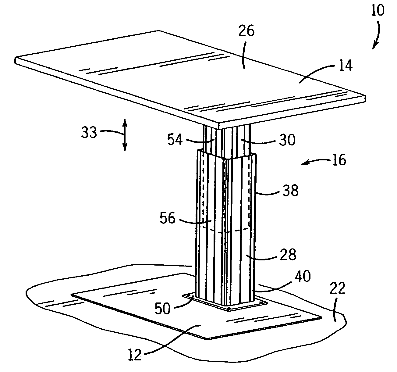
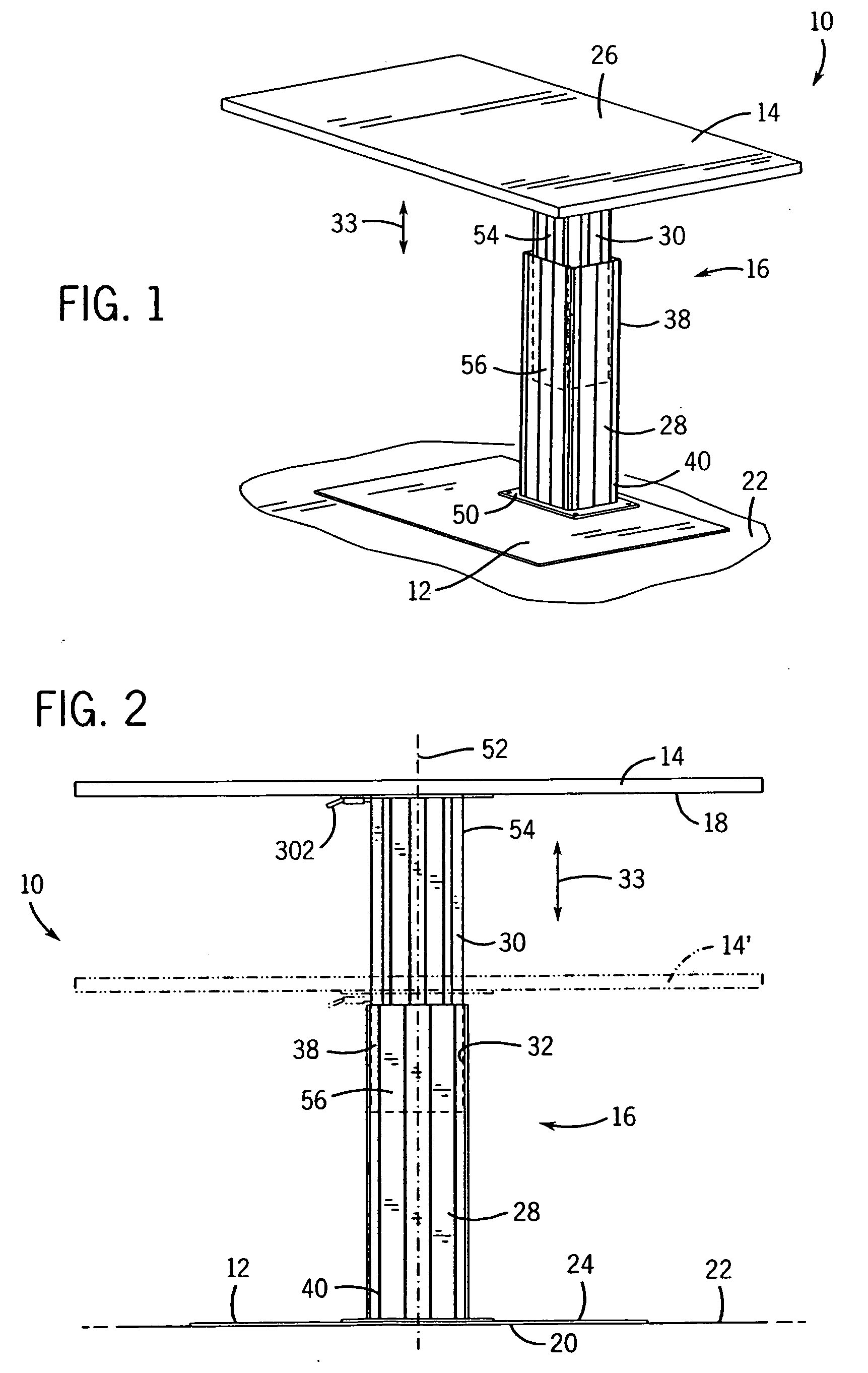
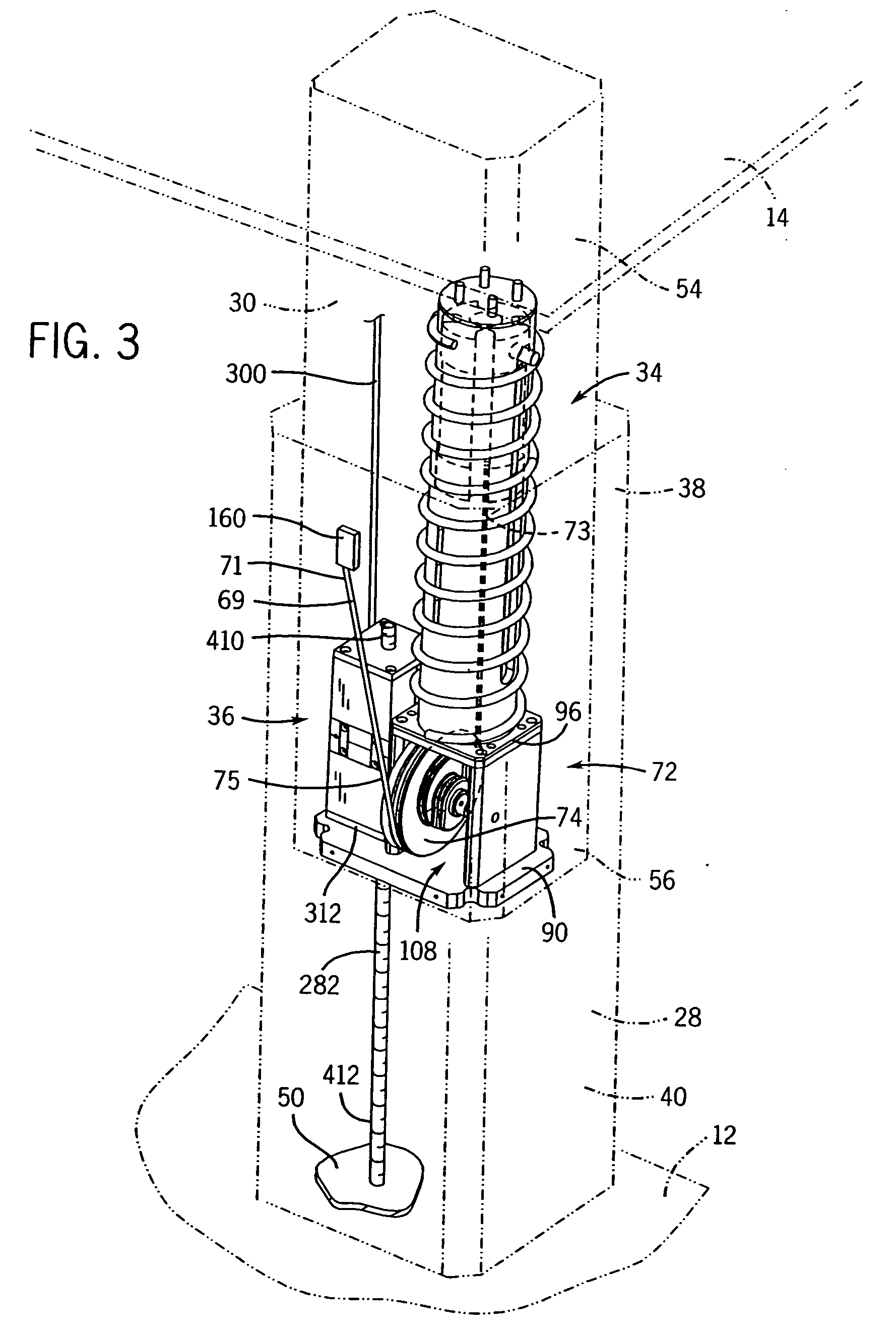
[0102] Referring now to the drawings wherein similar reference numerals correspond to similar elements throughout the several views and, more specifically, referring to FIGS. 1 and 2, at least some aspects of the present invention will be described in the context of an exemplary table assembly 10, inclu...


PUM


Abstract

A force adjustment assembly for use within a telescoping subassembly that includes a first elongated member and a second elongated member that is supported by the first elongated member for sliding motion along an extension axis, the subassembly further including a force equalizer assembly that includes a strand having first and second ends that are supported by the second and first elongated members, respectively, the adjustment assembly comprising a preloader supported by at least one of the first and second elongated members and supporting at least a portion of the strand, the preloader applying a preload force via the strand when the second elongated member is in a fully extended position and an adjuster for adjusting the preload force applied by the preloader.

Description

CROSS-REFERENCE TO RELATED APPLICATIONS [0001] This application is related to U.S. provisional patent application No. 60 / 637,031 which is titled “Load Compensator For Height Adjustable Table” which was filed on Dec. 17, 2004.STATEMENT REGARDING FEDERALLY SPONSORED RESEARCH OR DEVELOPMENT [0002] Not applicable. BACKGROUND OF THE INVENTION [0003] The inventive concepts described herein pertain to tables and, more particularly, to a vertical and adjustable support for tables or the like. [0004] Tables are used in many different environments for many different purposes. For instance, in an office environment, tables may be used in a partition space as a desk top to support a seated person, as a monitor support, as a conferencing table for seated conferees, as a standing conferencing table, as a work station supporting surface for a standing person, etc. Where tables are used for many different applications, ideally, the tables are constructed to have task specific heights that are ergon...

Claims


Application Information

Patent Timeline
Patent Type & Authority Applications(United States)
IPC IPC(8): F16M11/26F16F1/12
CPCA47B9/00A47B9/02
Inventor JONES, DAVID K.HEIDMANN, KURTANDRES, TODD
Owner STEELCASE INC
Why Eureka
Try Eureka