Passive lubricating prosthetic joint

a prosthetic joint and lubricating technology, applied in the field of orthopaedic surgery, can solve the problems of affecting the long-term affecting the performance of traditional prosthetic joints, and wear occurring at the interface of surfaces within joints, etc., to achieve the effect of facilitating motion, facilitating motion, and facilitating motion

Inactive Publication Date: 2007-08-02
WARSAW ORTHOPEDIC INC
View PDF30 Cites 33 Cited by
  • Summary
  • Abstract
  • Description
  • Claims
  • Application Information

AI Technical Summary

Benefits of technology

[0010] In another exemplary embodiment, a prosthetic joint includes a pair of substantially rigid members configured to engage first and second bones and an articulation member configured to facilitate motion between the pair of substantially rigid members. At least one of the substantially rigid members has one or more capillary channels configured to transport lubricious fluid to the articulation surface of the articulation member at least in part by capillary force.
[0011] In another exemplary embodiment, a prosthetic joint includes a pair of substantially rigid members configured to engage first and second bones and an articulation member configured to facilitate motion between the pair of substantially rigid members. At least one of the substantially rigid members has one or more fluid channels configured to allow lubricious fluid to flow proximate the articulation surface of the articulation member. A semi-permeable membrane is disposed proximate to the proximal end of at least one of the fluid channels.
[0012] In another exemplary embodiment, a method of replacing at least a portion of an intervertebral disc includes the steps of gaining access to the intervertebral disc; removing at least a portion of the intervertebral disc to create an intervertebral space; and inserting a prosthetic disc into the intervertebral space. The prosthetic disc includes a pair of substantially rigid members configured to engage adjacent vertebrae and an articulation member configured to facilitate motion between the members. At least one of the members has one or more capillary channels configured to transport lubricious fluid to the articulation surface of the articulation member at least in part by capillary force.
[0013] In another exemplary embodiment, a method of replacing at least a portion of an intervertebral disc includes the steps of gaining access to the intervertebral disc; removing at least a portion of the intervertebral disc to create an intervertebral space; and inserting a prosthetic disc into the intervertebral space. The prosthetic disc includes a pair of substantially rigid members configured to engage adjacent vertebrae and an articulation member configured to facilitate motion between the members. At least one of the members has one or more fluid channel configured to allow lubricious fluid to flow proximate the articulation surface of the articulation member. A semi-permeable membrane is disposed proximate the proximal end of at least one of the fluid channels and the articulation surface of the articulation member.
[0014] In another exemplary embodiment, an intervertebral prosthetic implant includes a pair of substantially rigid members configured to engage adjacent vertebrae and an articulation member configured to facilitate motion between the members. One of the members has at least one fluid channel configured to allow lubricious fluid to flow proximate the articulation surface of the articulation member. A semi-permeable membrane is disposed between the proximal end of at least one of the fluid channels and the articulation surface of the articulation member.

Problems solved by technology

Lubrication of a natural joint is a complex process that allows the joint to operate under a variety of conditions.
Wear occurring at the interface of surfaces within the joint can be a significant contributor to joint failure as well as to deleterious effects in collateral systems resulting from wear debris.
The long-term performance of traditional prosthetic joints has suffered from, among other things, a lack of an effective, long-term lubrication mechanism, whether by effectively delivering a synovial fluid substitute or by replicating the delivery of natural fluids to joint articulation surfaces.

Method used


Image

  • Passive lubricating prosthetic joint
  • Passive lubricating prosthetic joint
  • Passive lubricating prosthetic joint

Examples


Embodiment Construction

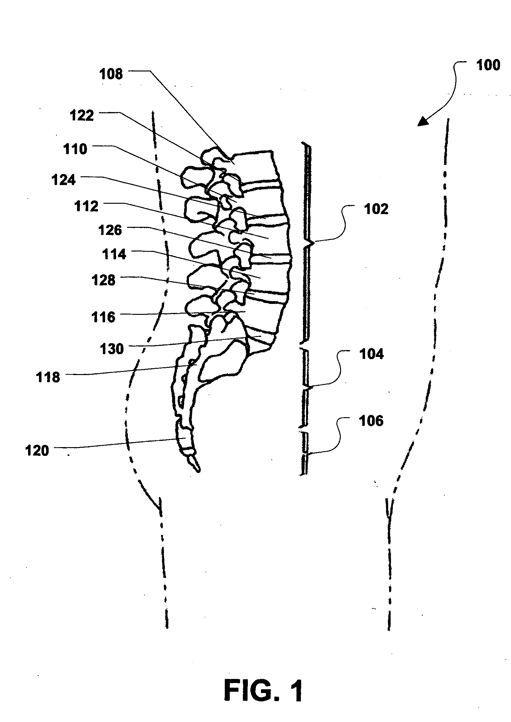
[0038] The teachings of the present application can find utility in various joint replacement situations, such as knee prosthetics, hip prosthetics and intervertebral prosthetic discs. With particular reference to intervertebral embodiments, FIG. 1 shows a portion of a vertebral column, designated 100. As depicted, the vertebral column 100 includes a lumbar region 102, a sacral region 104, and a coccygeal region 106. As is known in the art, the vertebral column 100 also includes a cervical region and a thoracic region. For clarity and ease of discussion, the cervical region and the thoracic region are not illustrated.

[0039] As shown in FIG. 1, the lumbar region 102 includes a first lumbar vertebra 108, a second lumbar vertebra 110, a third lumbar vertebra 112, a fourth lumbar vertebra 114, and a fifth lumbar vertebra 116. The sacral region 104 includes a sacrum 118. Further, the coccygeal region 106 includes a coccyx 120.

[0040] As depicted in FIG. 1, a first intervertebral lumbar ...


PUM

PropertyMeasurementUnit
osmotic pressureaaaaaaaaaa
capillary forceaaaaaaaaaa
monolithic structureaaaaaaaaaa

Abstract

Prosthetic joints, intervertebral prosthetic implants and methods of replacing intervertebral discs are provided. In an exemplary embodiment, a intervertebral prosthetic implant can include a pair of substantially rigid members and an articulation member having an articulation surface and configured to facilitate motion between the first and second members. The first member can be provided with at least one capillary channel configured to transport lubricious fluid proximate the articulation surface of the articulation member.

Description

BACKGROUND [0001] 1. Field of the Disclosure [0002] The present disclosure relates to the field of orthopedic surgery and has particular application to a total artificial joint and its post implantation performance. [0003] 2. Description of Related Art [0004] Lubrication of a natural joint is a complex process that allows the joint to operate under a variety of conditions. Such conditions can include: maximum joint surface velocity and sudden and prolonged applied load. Articular cartilage is filled with synovial fluid that is squeezed from the surface upon loading. At high loads and low velocity, boundary lubrication is present as a means to protect the surfaces and minimize their contact. At higher velocities, fluid film lubrication is generated between the surfaces because of pressure build-up, which substantially completely separates the surfaces. Since cartilage is highly deformable under pressure, this deformation can enhance the thickness of the fluid film, a process which is...

Claims


Application Information

Patent Timeline
Patent Type & Authority Applications(United States)
IPC IPC(8): A61F2/44A61F2/30A61F2/38A61F2/32
CPCA61F2/30721A61F2310/0088A61F2/38A61F2/4425A61F2/4611A61F2002/30649A61F2002/30652A61F2002/30672A61F2002/30673A61F2002/30785A61F2002/30884A61F2310/00017A61F2310/00023A61F2310/00029A61F2310/00131A61F2310/00149A61F2310/00155A61F2310/00407A61F2310/00562A61F2/30742
Inventor HEINZ, ERIC S.
Owner WARSAW ORTHOPEDIC INC
Why Eureka
Try Eureka