Testing printed circuit boards of disk drives and servo track writers

a technology of disk drives and servo track writers, which is applied in the direction of printed circuit testing, measurement devices, instruments, etc., can solve the problems of reducing test accuracy, incurring extra costs, and not being able to use small disk drive pcbs

Inactive Publication Date: 2006-07-06
GS MAGIC
View PDF14 Cites 10 Cited by
  • Summary
  • Abstract
  • Description
  • Claims
  • Application Information

AI Technical Summary

Benefits of technology

[0008] One or more embodiments of the present invention solve one or more of the above-identified problems. In particular, one embodiment of the present invention is a method for testing a reading function of a printed circuit board of a disk drive or a servo track writer that comprises: (a) providing a test pattern; (b) processing the test pattern to generate a digital signal series; (c) differentiating the digital signal series to provide a differentiated signal series; (d) applying the differentiated signal series as input to the printed circuit board; and (e) comparing an output from the printed circuit board with the test pattern. In addition, another embodiment of the present invention is a method for testing a writing function of a printed circuit board of a disk drive or a servo track writer that comprises: (a) providing a test pattern; (b) applying the test pattern as input to the printed circuit board to generate a digital signal series; (c) differentiating the digital signal series to provide a differentiated signal series; (d) processing the differentiated signal series; and (e) comparing an output from step (d) with the test pattern.

Problems solved by technology

However, such a method of testing requires significant room on the PCBs and, therefore, it is not applicable for use with small disk drive PCBs which do not have sufficient space for test pads.
This done because of test costs.
Problems encountered in directly operating disk drives to test disk drive PCBs and in directly operating STWs to test STW PCBs include: (a) loading / unloading testing heads for testing disk drive PCBs or STW PCBs is time consuming; (b) loading / unloading testing heads might cause damage and therefore might incur extra cost; (c) testing heads degrade after being used a number of times and therefore reduce test accuracy; and (d) replacing degraded testing heads incurs extra cost.
Although simulation methods have been used in large disk drives, the equipment required to generate appropriate signals for simulation is expensive.

Method used


Image

  • Testing printed circuit boards of disk drives and servo track writers
  • Testing printed circuit boards of disk drives and servo track writers
  • Testing printed circuit boards of disk drives and servo track writers

Examples


Embodiment Construction

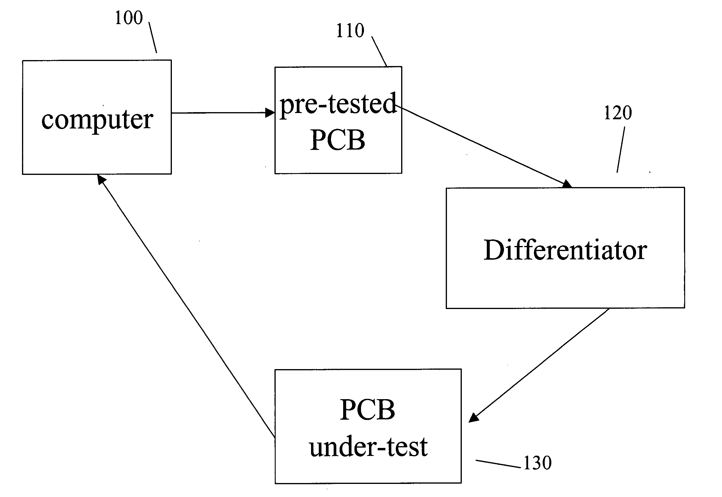
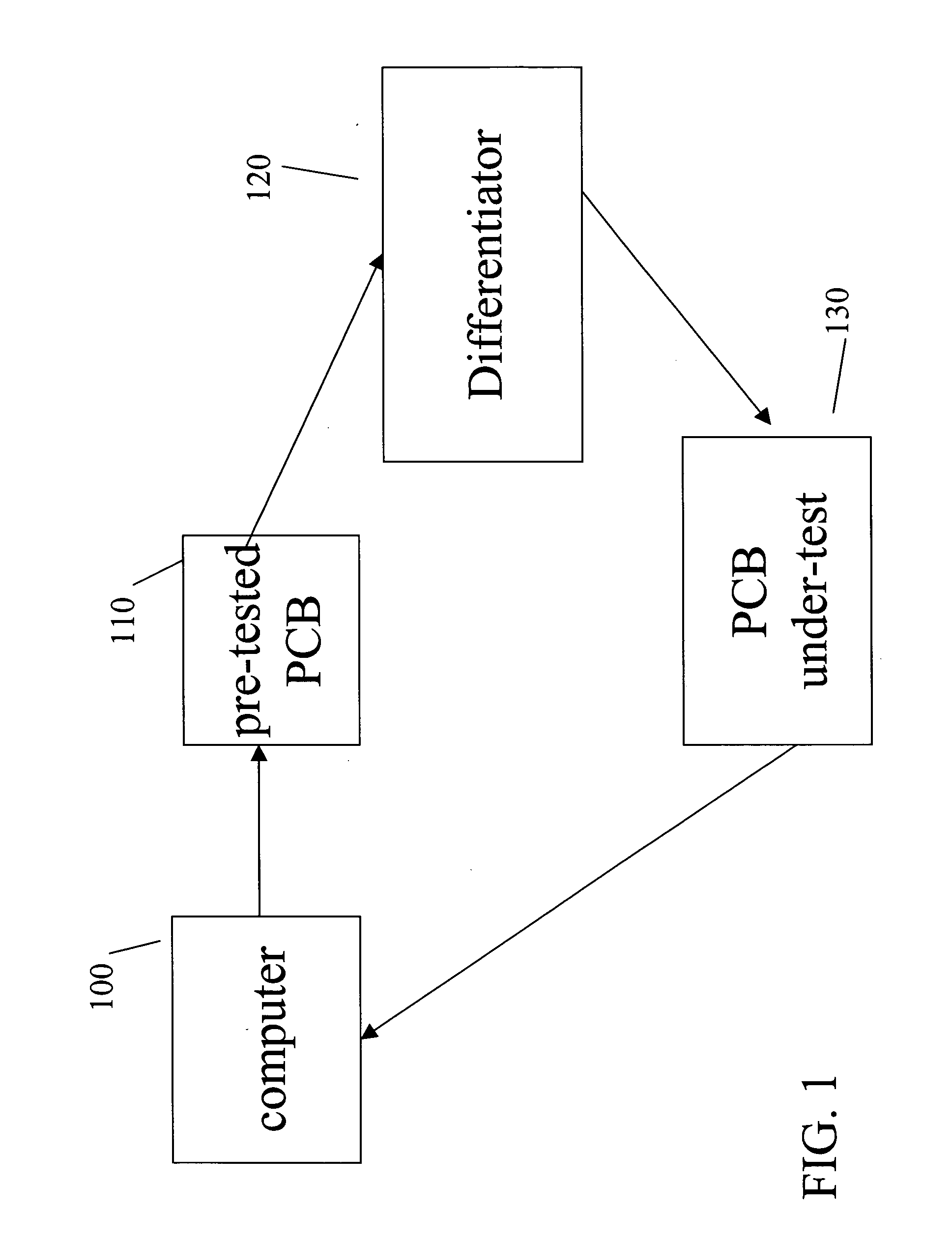
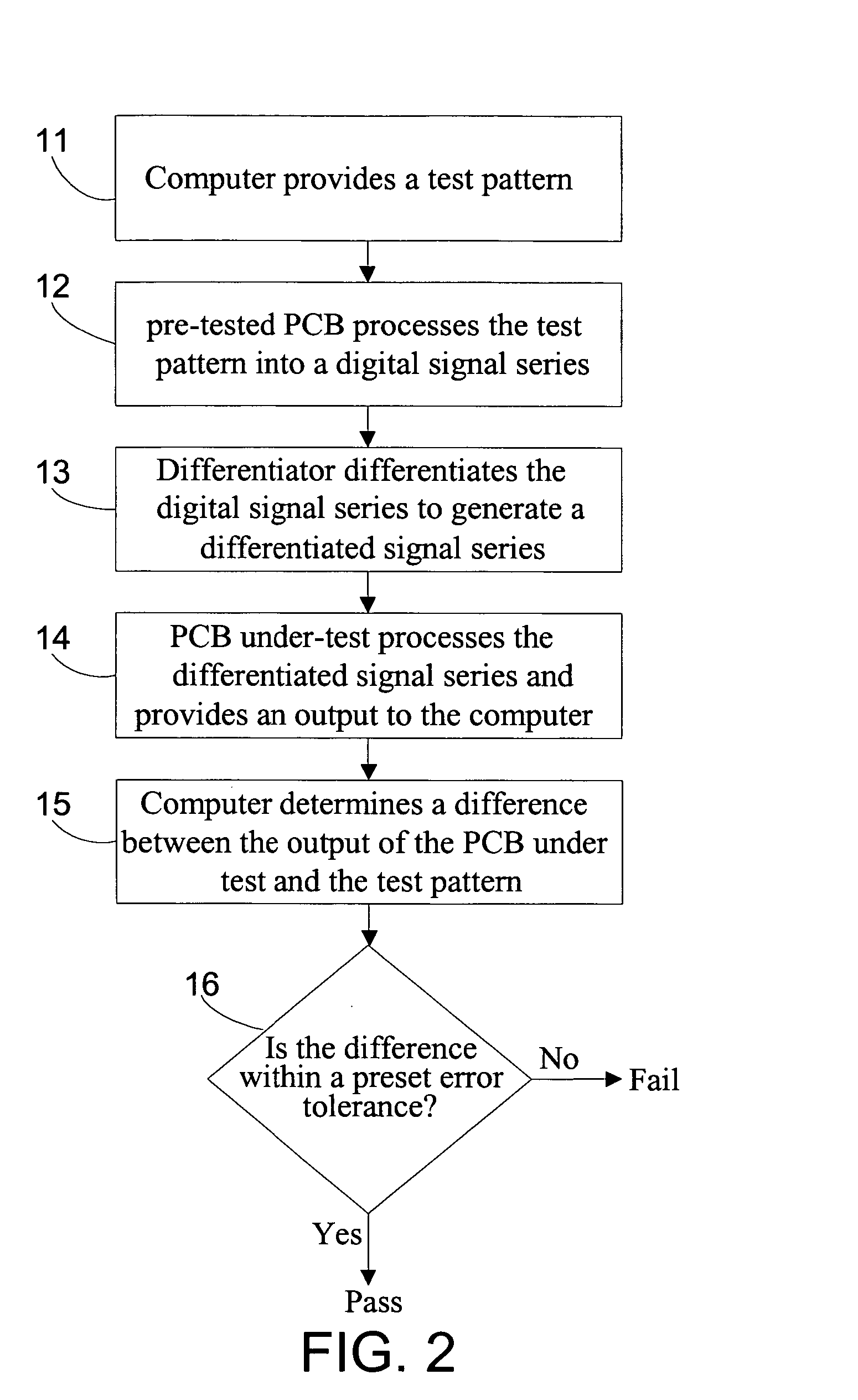
[0015]FIG. 1 shows an apparatus that is fabricated in accordance with one or more embodiments of the present invention for use in testing a reading function of printed circuit boards (PCBs) of disk drives or PCBs of servo track writer (STWs); and FIG. 2 is a flowchart of a method that is fabricated in accordance with one or more embodiments of the present invention (which, for example and without limitation, utilize the apparatus shown in FIG. 1) for testing the reading function of the disk drive PCBs or the STW PCBs.

[0016] The method starts with step 11 (shown in FIG. 2), at which computer 100 (shown in FIG. 1) outputs: (a) a test pattern (for example and without limitation, computer 100 acts as a pattern generator); and (b) optionally, and preferably, a command that will be intepreted by pre-tested PCB 110 as a command to process the test pattern (for example, and without limitation, a “write” command) into a digital signal series. As is known to those of ordinary skill in the ar...


PUM


Abstract

One embodiment of the present invention is method for testing a reading function of a printed circuit board of a disk drive or a servo track writer that includes: (a) providing a test pattern; (b) processing the test pattern to generate a digital signal series; (c) differentiating the digital signal series to provide a differentiated signal series; (d) applying the differentiated signal series as input to the printed circuit board; and (e) comparing an output from the printed circuit board with the test pattern.

Description

TECHNICAL FIELD OF THE INVENTION [0001] One or more embodiments of the present invention relate to method and apparatus for testing disk drives, and more particularly, to method and apparatus for testing printed circuit boards (PCBs) of disk drives and PCBs of servo track writers (STWs). BACKGROUND OF THE INVENTION [0002] In disk drive manufacturing, printed circuit boards (PCBs) of a disk drive have to be tested to ensure that such PCBs will, for example, correctly: (a) process data read from a disk; and (b) process data to be written onto the disk. In addition, PCBs of servo track writers (STWs) have to be tested to ensure that the STW PCBs will correctly process servo data read from / written onto a disk. [0003] Conventionally, PCBs of large disk drives, such as 2.5″ and 3.5″ disk drives, are tested by: (a) adding test pads in the PCB layout design; and (b) using functional testers to probe the test pads. However, such a method of testing requires significant room on the PCBs and, ...

Claims


Application Information

Patent Timeline
Patent Type & Authority Applications(United States)
IPC IPC(8): G01R31/26
CPCG01R31/2803G01R31/31707
Inventor TON-CHURO, HUANG
Owner GS MAGIC
Why Eureka
Try Eureka