Fusing unit and image forming apparatus

a technology of forming apparatus and fusing device, which is applied in the direction of electrographic process apparatus, instruments, optics, etc., can solve the problems of distortion in the elastic layer of the heating roller, high cost of fusing device, and high cost of fusing device, and achieve the effect of creep deformation

Inactive Publication Date: 2006-07-06
SEIKO EPSON CORP
View PDF8 Cites 12 Cited by
  • Summary
  • Abstract
  • Description
  • Claims
  • Application Information

AI Technical Summary

Benefits of technology

[0045] According to a first embodiment of the invention in which the sliding member is disposed between the belt stretching member and the pressing roller and slides along the periphery of the pressing roller, and the belt stretcher and the sliding member are brought into contact with the heating roller through the heat-resistant belt, the axial distortion of the belt stretching member and creep deformation can be prevented and a uniform and stable fusing nip is formed over the all axial direction.
[0046] According to a second embodiment of the invention in which the sliding member is disposed between the belt stretching member and the pressing roller and slides along the periphery of the pressing roller to be brought into contact with the heating roller, and the belt stretching member is disposed at a position where the sheet medium is guided to a nip portion to be brought in noncontact with the heating roller through the heat-resistant belt in advancing the sheet medium, a stable and uniform nip can be formed over an entire face in an axial direction, an introducing port portion in which the sheet medium is smoothly advanced can be formed, and the sheet medium S can advance smoothly. Accordingly, it is prevented that a sheet medium S is not advanced smoothly and is fused in a state where a front end of the sheet medium S is folded for the reason why the fusing pressure is large at the initial position where the sheet medium S goes into the fusing nip.

Problems solved by technology

This renders the fusing device expensive as well as complicated and bulky; and inevitably makes an image forming apparatus equipped with the fusing device complicated, bulky, and expensive.
This undesirably entails a longer so-called warm-up time which elapses from when power is turned on until fusing becomes feasible.
The heat-resistant belt is wrapped around the heating roller over only an angle which enables formation of a nipping portion, and pressure which is greater than that applied to the other areas is locally applied to the heat-resistant belt at the exit of the nipping portion, to thus cause distortion in the elastic layer of the heating roller.
However, the sheet medium output along the distortion of the elastic layer is curled in imitation of this distortion or is subjected to deformation, such as occurrence of wrinkles, caused by local high pressure.
However, the heat capacity of the rollers is large, and, hence, consumption of a long warm-up time is undesirably required.
In addition, the sheet medium, having passed through the long nipping portion formed by deforming the rollers with pressure, undergoes stress derived from the pressure, as in the case of the former fusing device, which in turn causes deformation of the sheet medium, such as occurrence of a curl or wrinkles.
As a result, the structure of the heat-roller-type fusing device can be subjected to simplification, downsizing, and cost-saving.
However, the structures are not sufficient for forming a stable nipping portion in the axial direction of the heating roller and that of the pressing roller; namely, over the entire longitudinal area of the heating roller and that of the pressing roller.
For these reasons, under the present circumstances, the nipping portion is under influence of such deformation, and difficulty is encountered in preventing the nipping portion from becoming unstable.
Thus, enhancement of the fusing characteristic cannot be achieved.
In addition, there may arise a case where creeping deformation arises under influence of the heating roller which is heated to a temperature as high as about 200° C. Particularly, when the stretcher is formed from a plastic material having low thermal capacity, on the assumption that the stretcher is effective for shortening a warm-up time, the phenomenon of occurrence of deflection or deformation has become noticeable, which is not preferable for forming a stable nipping portion.

Method used


Image

  • Fusing unit and image forming apparatus
  • Fusing unit and image forming apparatus
  • Fusing unit and image forming apparatus

Examples


Embodiment Construction

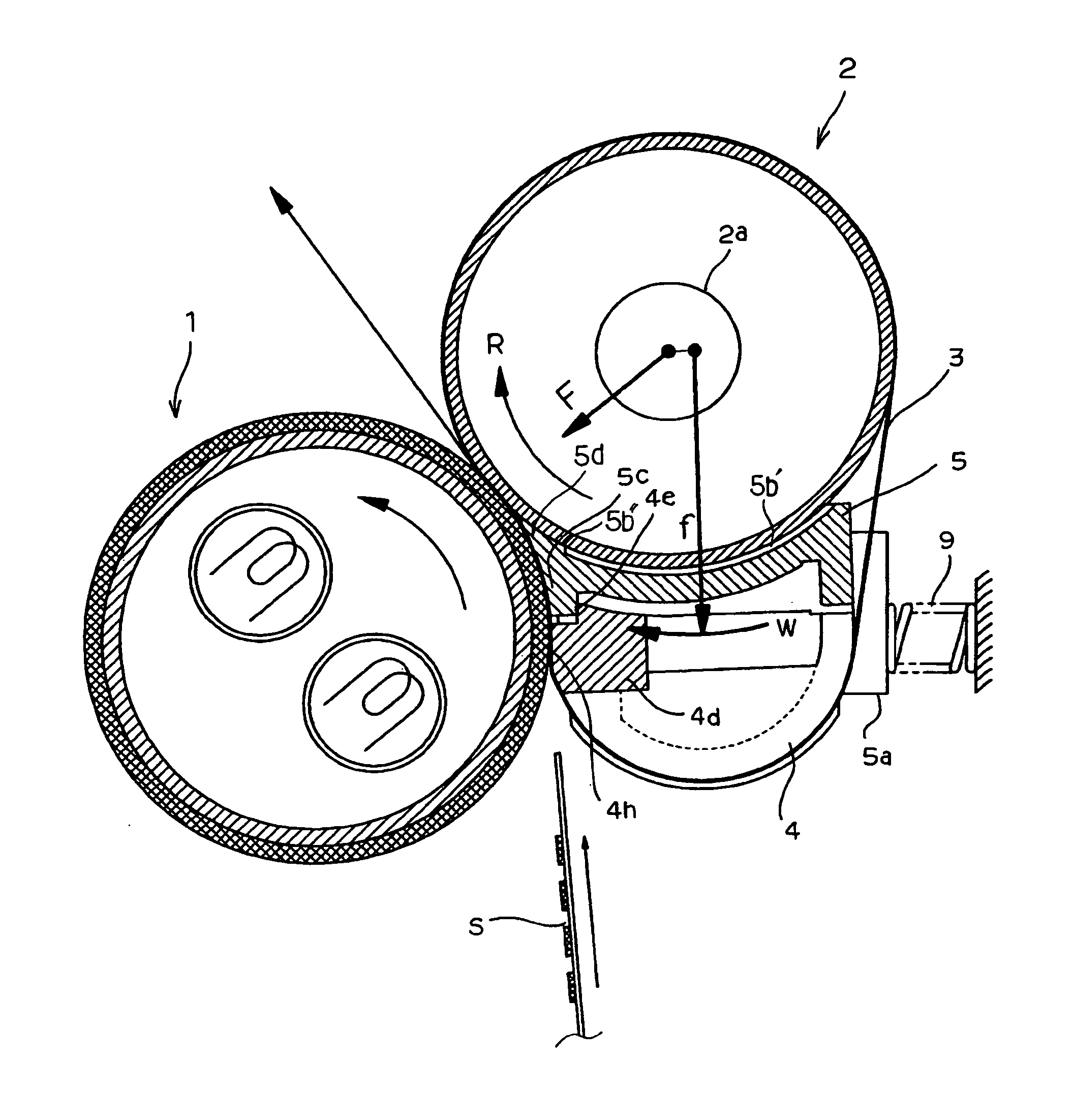
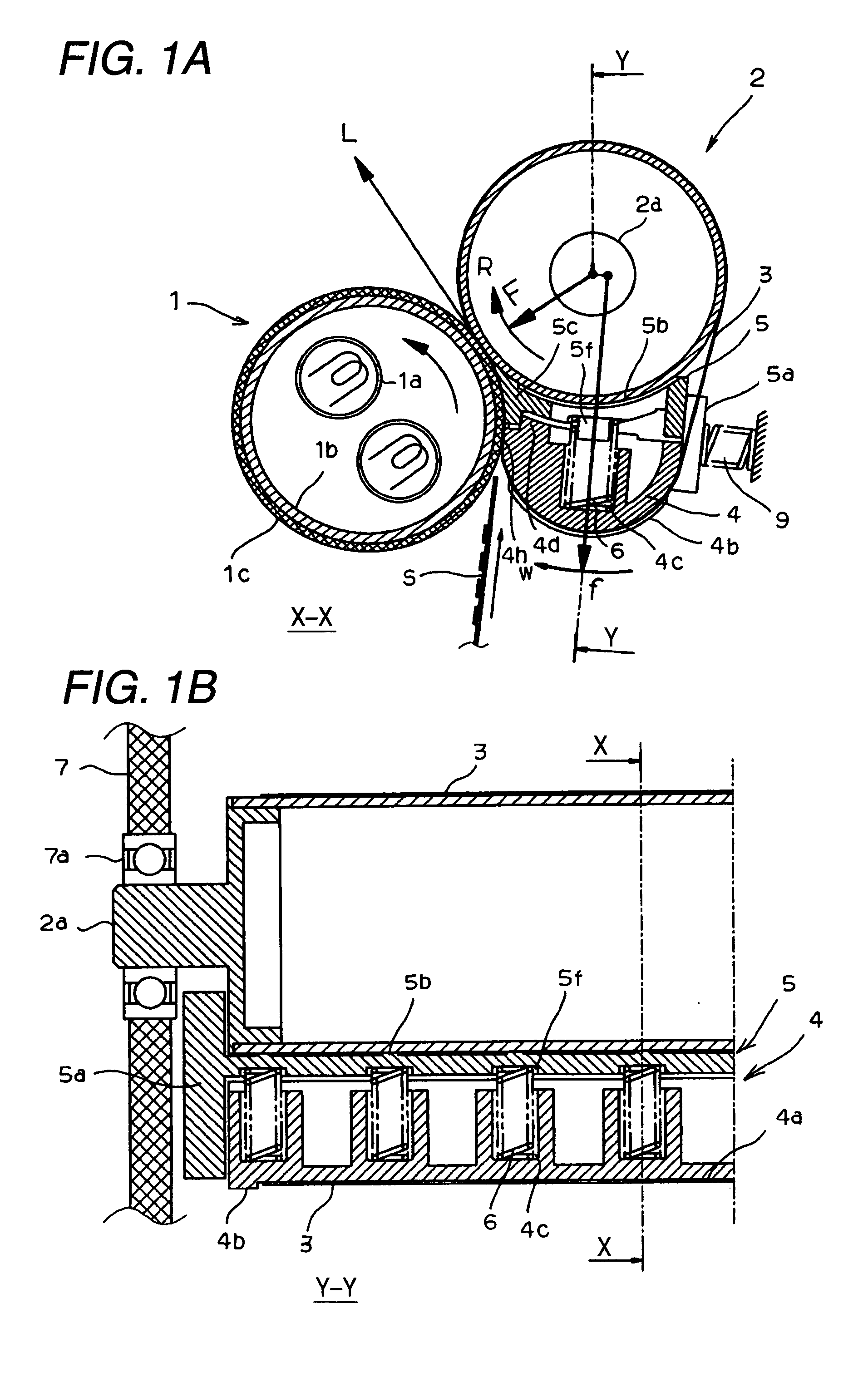
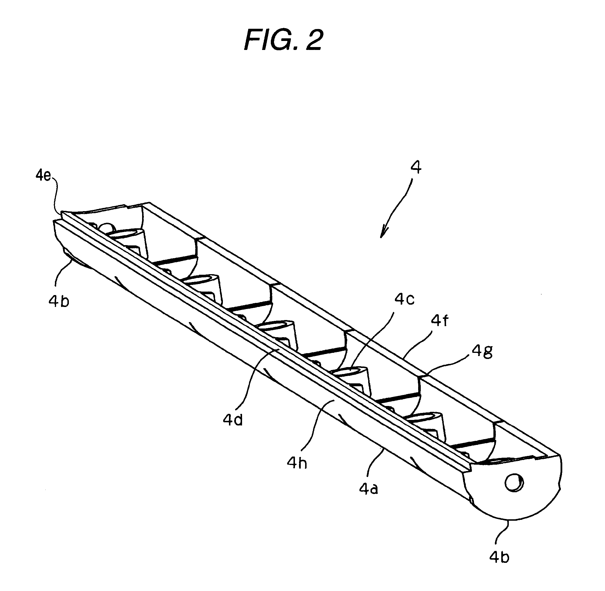
[0063] A first embodiment of the invention will be explained in reference to the drawings as follows. FIG. 1 shows an embodiment of a fusing unit according to the invention, FIG. 1(A) is a sectional view taken along a line X-X of FIG. 1(B) and viewed in an arrow direction, and FIG. 1(B) is a sectional view taken along a line Y-Y of FIG. 1(A), in which a right half of the apparatus is omitted. FIG. 2 is a perspective view of a belt stretching member of the fusing unit shown in FIG. 1 viewed from the side of a pressing roller thereof, FIG. 3 is a perspective view of a nip pressing member of the fusing unit shown in FIG. 1 viewed from the side of the pressing roller, and FIG. 4 is a view enlarging to show a fusing nip portion of the fusing unit shown in FIG. 1. In the drawings, numeral 1 designates a heating roller, numeral 2 designates a pressing roller, numeral 3 designates a heat-resistant belt, numeral 4 designates a belt stretching member, notation 4a designates a belt sliding fac...


PUM


Abstract

A fusing unit for fusing a nonfused toner image formed on a sheet medium, including: a heating roller; a pressing roller pressed to the heating roller; a heat-resistant belt which is wrapped around an outer periphery of the pressing roller and travels while being nipped at a nip portion between the pressing roller and the heating roller; a belt stretching member which stretches the heat-resistant belt; and a sliding member which is disposed between the belt stretching member and the pressing roller and slides along the outer periphery of the pressing roller, wherein the sliding member is disposed to be brought into contact with the heating roller through the heat-resistant belt at a contact portion.

Description

BACKGROUND OF THE INVENTION [0001] 1. Technical Field of the Invention [0002] The present invention relates to a fusing unit which fuses an nonfused toner image formed on a sheet medium and includes a heating roller, a pressing roller pressed to the heating roller, a heat-resistant belt which is wrapped around an outer periphery of the pressing roller and travels while being nipped between the heating roller and the pressing roller, and a belt stretching member for stretching the heat-resistant belt and an image forming apparatus. [0003] 2. Description of the Related Art [0004] The following two types of fusing devices have been proposed as a heating-roller-type fusing device which is mounted on an image forming apparatus such as a copier, a printer, or a facsimile and which fuses a nonfused toner image on a transfer material through contact thermofusing. Namely, one type of fusing device comprises a heating roller whose surface is coated with an elastic body and which has a built-i...

Claims


Application Information

Patent Timeline
Patent Type & Authority Applications(United States)
IPC IPC(8): G03G15/20
CPCG03G15/2064G03G2215/2009G03G15/2028G03G15/2053G03G2215/2022
Inventor ARUGA, TOMOEIKUMA, KEN
Owner SEIKO EPSON CORP
Why Eureka
Try Eureka