Electric oil pump system

a technology of electric oil pump and oil pump, which is applied in the direction of machines/engines, liquid fuel engines, positive displacement liquid engines, etc., can solve the problems of warpage of the stator, fluctuation of rotation, and creep deformation of the contact etc., and achieve the effect of creep deformation of the resin mold portion of the stator of the motor

Active Publication Date: 2013-08-08
JTEKT CORP
View PDF9 Cites 15 Cited by
  • Summary
  • Abstract
  • Description
  • Claims
  • Application Information

AI Technical Summary

Benefits of technology

[0007]The invention provides an electric oil pump system in which creep deformation of a resin mold portion of a stator of a motor is prevented and pump discharge pressure is stabilized.

Problems solved by technology

This contact portion may be creep-deformed due to age deterioration.
Thus, for example, warpage of the stator and loosening of bolts may occur.
As a result, a rotary shaft of the electric motor may cause rotation fluctuation.
Further, there may be caused contact noise between internal teeth and external teeth in a rotor portion of the oil pump, operating noise of the electric oil pump system due to pulsation of pump discharge pressure, and reduction in pump output (pressure, flow rate).

Method used


Image

  • Electric oil pump system
  • Electric oil pump system
  • Electric oil pump system

Examples


Embodiment Construction

[0012]Hereinafter, embodiments of the invention will be described with reference to the accompanying drawings.

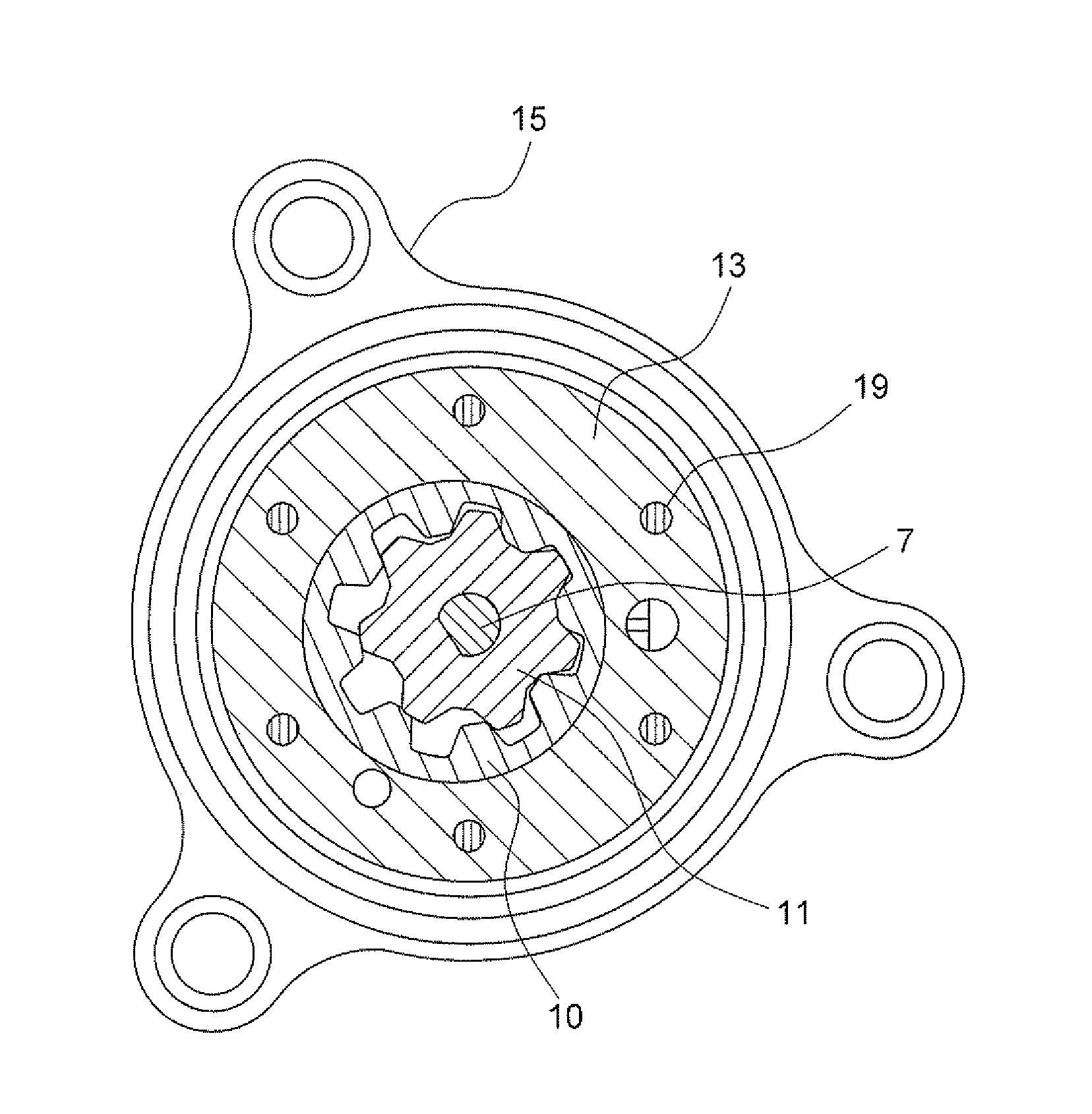
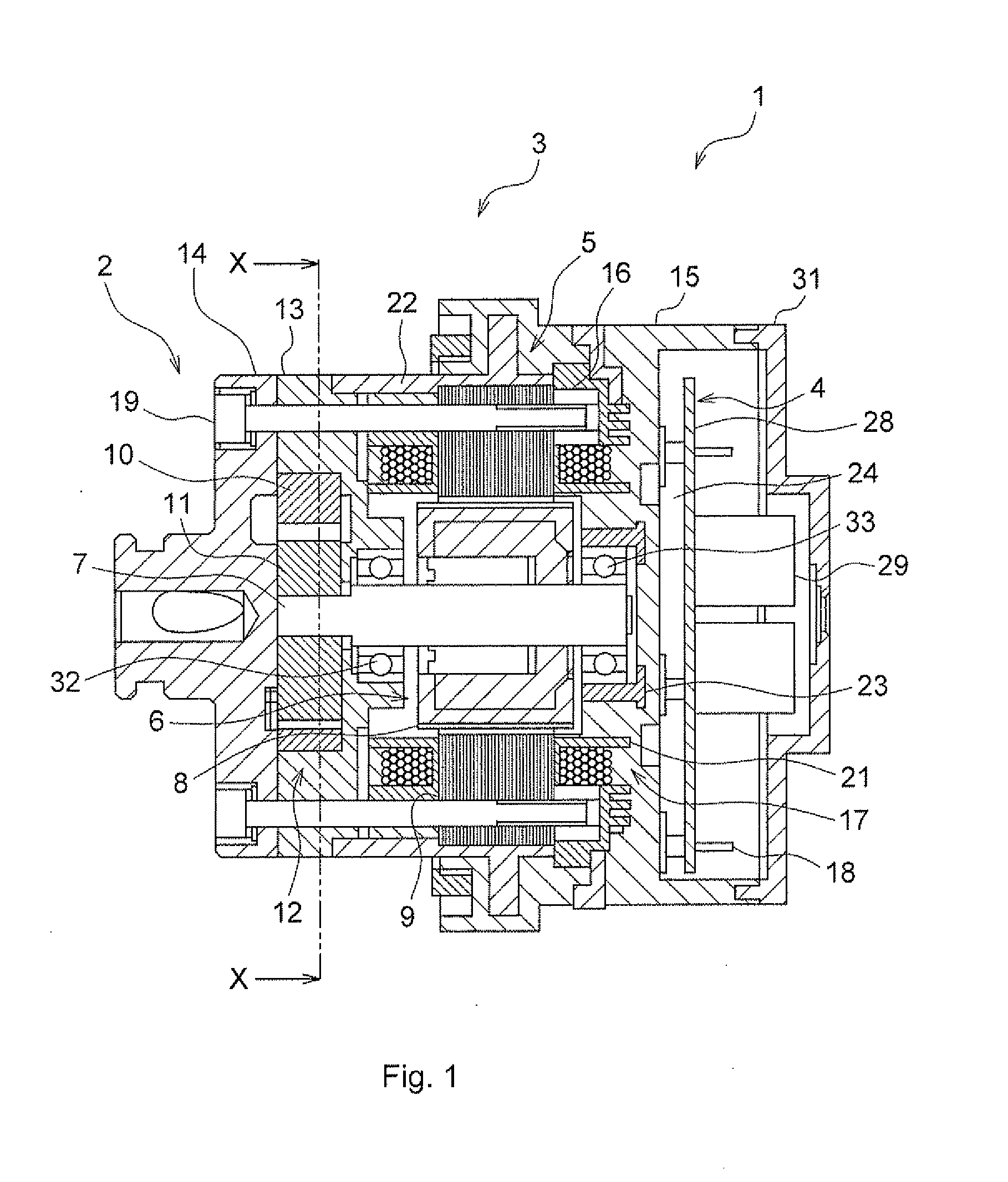
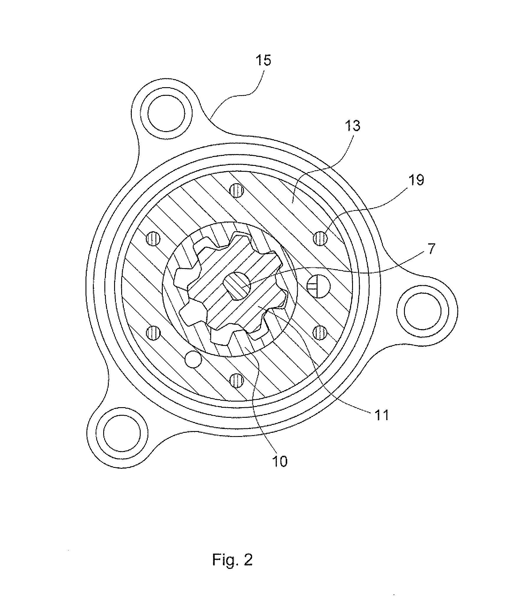
[0013]FIG. 1 is an axial sectional view illustrating the schematic configuration of an electric oil pump system according to an embodiment of the invention. FIG. 2 is a sectional view illustrating a rotor portion of an oil pump, taken along the line X-X in FIG. 1. As shown in FIG. 1 and FIG. 2, an electric oil pump system 1 is used as a hydraulic pump for a transmission of an automobile, and includes an oil pump (e.g. an internal gear pump) 2, and an electric motor (hereinafter, referred to as “brushless motor”) 3 that rotates the oil pump 2. The electric motor 3 and the oil pump 2 are arranged next to each other and assembled together. Further, a controller 4 is also incorporated in a motor housing 15. The brushless motor 3 shown in FIG. 1 is a sensorless brushless motor.

[0014]In the oil pump 2, a pump inner rotor (hereinafter, referred to as “inner rotor”) 11 with external...


PUM


Abstract

A stator is fixedly fastened at its outer periphery by a cylindrical and thin metal collar. One end of the collar is engaged with a pump housing. Multiple metal nuts are embedded in insulators fitted to stator cores through insert molding. The stator of a brushless motor is fixed by screwing bolts passed through the pump housing from a pump plate, to nuts embedded in the insulators.

Description

INCORPORATION BY REFERENCE / RELATED APPLICATION[0001]The application claims priority to Japanese Patent Application No. 2012-020722 filed on Feb. 2, 2012 the disclosure of which, including the specification, drawings and abstract, is incorporated herein by reference in its entirety.BACKGROUND OF THE INVENTION[0002]1. Field of the Invention[0003]The invention relates to an electric oil pump system.[0004]2. Description of Related Art[0005]There has been proposed an electric oil pump system that is a combination of an oil pump that circulates fluid (oil) and an electric motor that drives the oil pump. The electric motor includes a rotor that rotates and a stator that is fixedly arranged radially outward of the outer peripheral face of the rotor. The rotor is formed by arranging a plurality of permanent magnets on the outer peripheral face of a rotary drive shaft along its circumferential direction. The rotary drive shaft is a rotary shaft that is shared by the electric motor and the oil...

Claims


Application Information

Patent Timeline
Patent Type & Authority Applications(United States)
IPC IPC(8): F04C11/00
CPCF01C21/10F04C2/102F04C2240/805F04C15/008F04C2240/40F04C11/008
Inventor MIYAKI, JUNICHINISIZAKI, KATSUTOSHIOONO, YOSHIHIROKANDA, NAOTAKE
Owner JTEKT CORP
Why Eureka
Try Eureka