Compressed seal for a movable joint

a compression seal and movable joint technology, applied in the direction of screw threaded joints, adjustable joints, pipe joints, etc., can solve problems such as member failur

Inactive Publication Date: 2006-01-10
BETTINGER DAVID S
View PDF13 Cites 11 Cited by
  • Summary
  • Abstract
  • Description
  • Claims
  • Application Information

AI Technical Summary

Benefits of technology

[0027]It will also be recognized by one skilled in the art that the current invention may be combined with rotator joints a

Problems solved by technology

In general, PMC members that must maintain high stress levels for extended periods of mon

Method used


Image

  • Compressed seal for a movable joint
  • Compressed seal for a movable joint
  • Compressed seal for a movable joint

Examples


Embodiment Construction

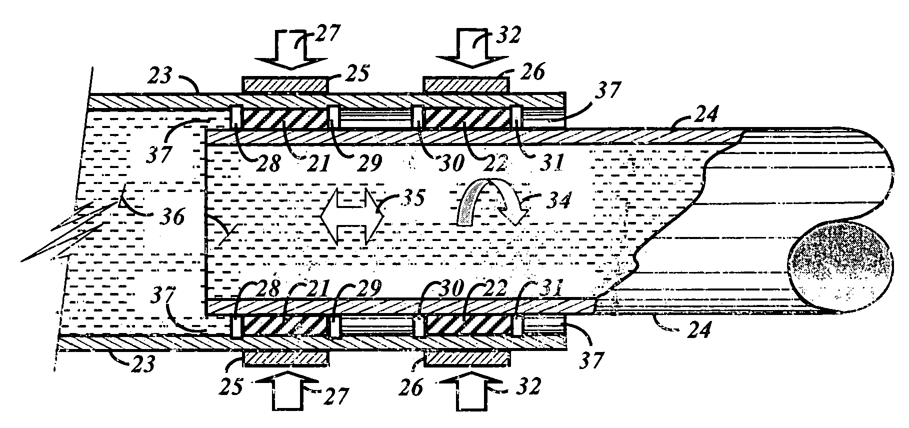
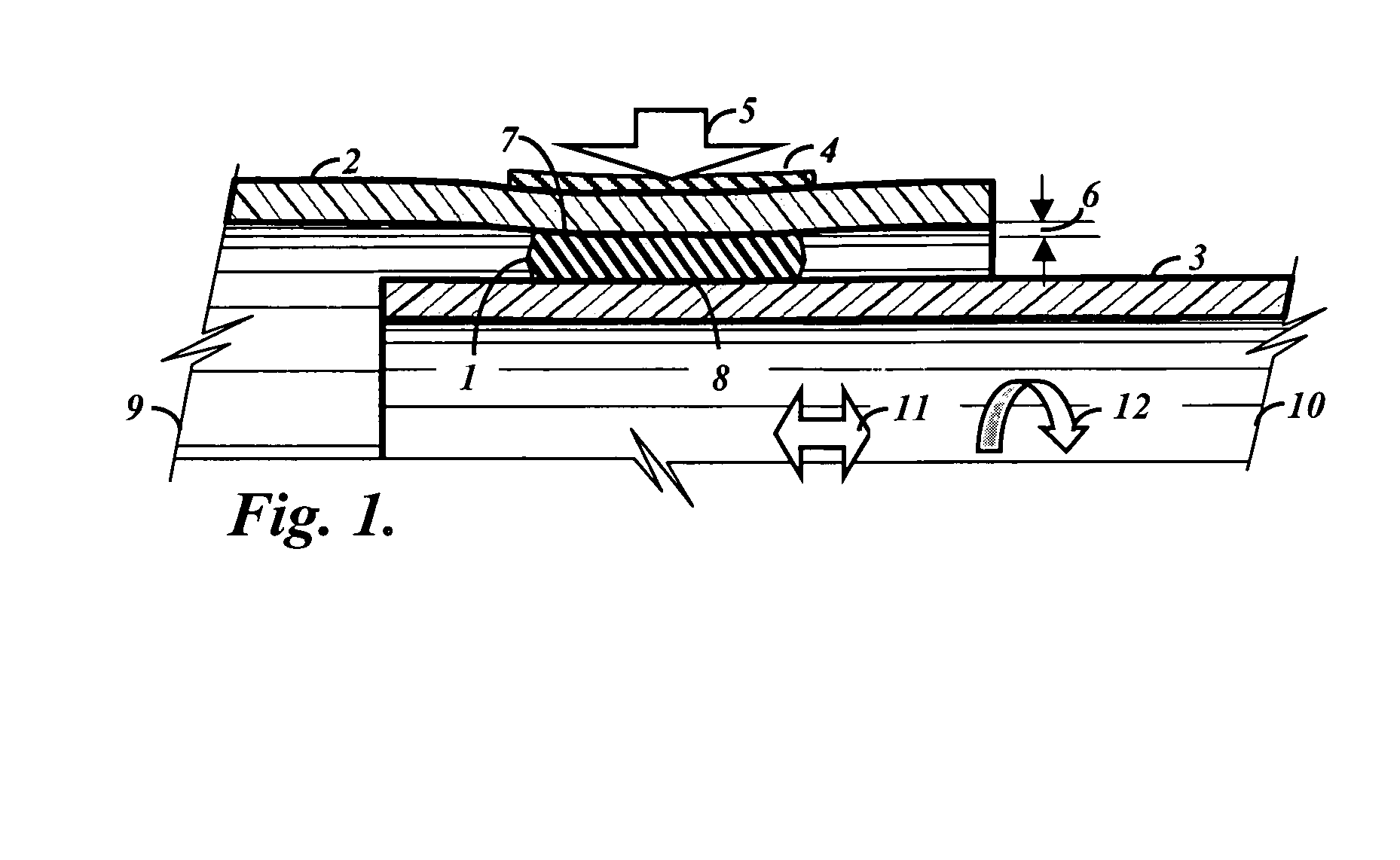
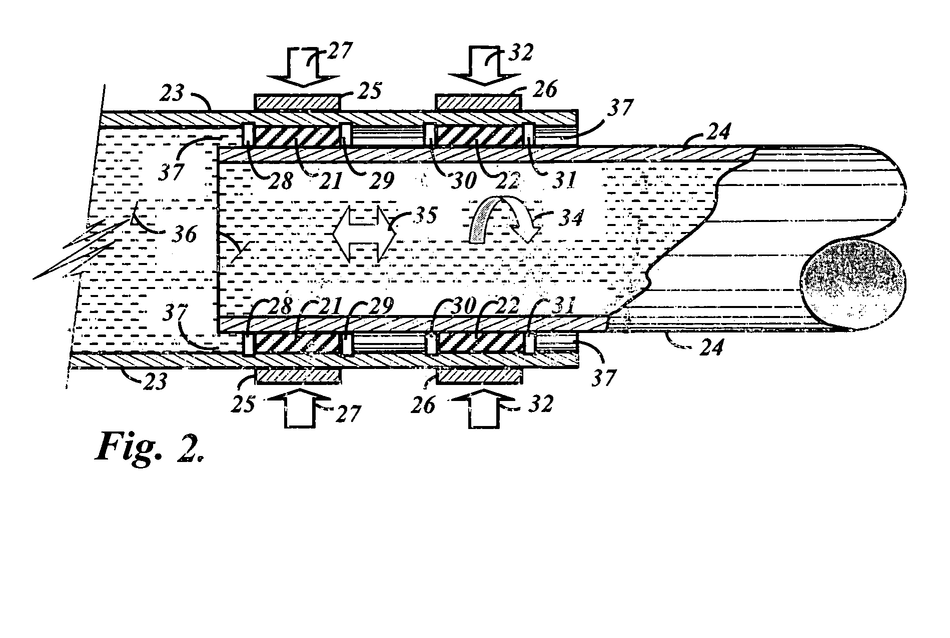
[0030]In FIG. 1 a compressed seal expansion joint is shown comprising at least one generally cylindrical resilient and elastic seal 1 disposed in an annular packing chamber defined between telescopically arranged outer 2 and inner 3 pipe members and an outer circumferentially tensioned band and clamp 4 positioned longitudinally over the generally cylindrical resilient and elastic seal 1 and selected to produce a compressive force 5 to radially deflect the outer pipe member and thereby compress and deflect the generally cylindrical resilient and elastic seal with a deflection shown at 6 so that the outer and inner pipe members and the generally cylindrical resilient and elastic seal create and maintain a bearing and static and dynamic friction-loaded sealed relationship between the generally cylindrical resilient and elastic seal and outer and inner pipe member surfaces 7, 8 for fluid flow at varying temperatures between adjacent ends of two conduits 9, 10 during axial sliding 11 and...


PUM


Abstract

A compressed seal expansion joint for fluidically connecting in a sealed relationship adjacent ends of two conduits adapted for carrying fluids of varying temperatures, the expansion joint comprising telescopically arranged outer and inner pipe members adapted to be connected to each of the conduits, the outer pipe member defining an annular packing chamber opening through its inner surface for containing at least two cylindrical guide rings disposed at opposite ends of the chamber, the rings being of a generally rectangular cross section having their long faces longitudinal to the members axis and selected of an elastic and semi-plastic packing composition pressurized by tensioned hoop bands circumscribing the outer pipe member and selected to elastically deform the outer pipe member and communicate a circumferentially compressive force to the guide rings so as to create bearing and frictional loadings and seal between guide ring surfaces and the pipe member surfaces during axial and rotational relative pipe member movement.

Description

FEDERAL RESEARCH STATEMENT[0001]The development effort for this current invention was funded under US Army Space and Missile Defense SBIR Topic Number BMDO00-013, Contract Number DASG60-01-C-0068.BACKGROUND OF INVENTION[0002]This invention relates to a pipe joint and coupling for tubular fluid conduits and to dynamic inter-fitted pipe members and seals in telescoping relationship constructed to provide for axial positional movement relative to a member and remain fluid-pressure-tight, and more particularly to such a joint where the external and outer member is elastically deformed by an external hoop tensile member providing elastic spring biasing to compressively pressure and assure circumferential contact between members and seals for maintaining a leak-proof seal and fitting.[0003]Such expansion joints possessing specific bearing structures such as compressed resilient seals accommodate relative motion between and positional adjustment of one or more pipe members to compensate fo...

Claims


Application Information

Patent Timeline
IPC IPC(8): F16L27/00F16L27/12
CPCF16L27/12F16L27/127
Inventor BETTINGER, DAVID S.
Owner BETTINGER DAVID S
Why Eureka
Try Eureka