Swing arm supporting structure for motorcycles

a technology for swing arms and motorcycles, which is applied in the direction of bicycles, cycle equipment, transportation and packaging, etc., can solve the problems of difficult mounting work of the rear arm b>14/b> to the rear arm bracket b>7/b>, and achieve the effect of improving the swing arm supporting structure, easy mounting and dismounting of the pivot shaft, and increasing the number of components

Active Publication Date: 2006-07-13
HONDA MOTOR CO LTD
View PDF3 Cites 21 Cited by
  • Summary
  • Abstract
  • Description
  • Claims
  • Application Information

AI Technical Summary

Benefits of technology

[0014] It is an object of the present invention to restrain an increase in the number of components and enable an easy mounting and dismounting of the pivot shaft by improving the swing arm supporting structure in a motorcycle.

Problems solved by technology

However, since the head portion 14c or the frame portions 7e, 7f are not provided with a structure for positioning them with respect to each other, they are difficult to position, which makes the mounting work of the rear arm 14 to the rear arm bracket 7 difficult.

Method used


Image

  • Swing arm supporting structure for motorcycles
  • Swing arm supporting structure for motorcycles
  • Swing arm supporting structure for motorcycles

Examples


Embodiment Construction

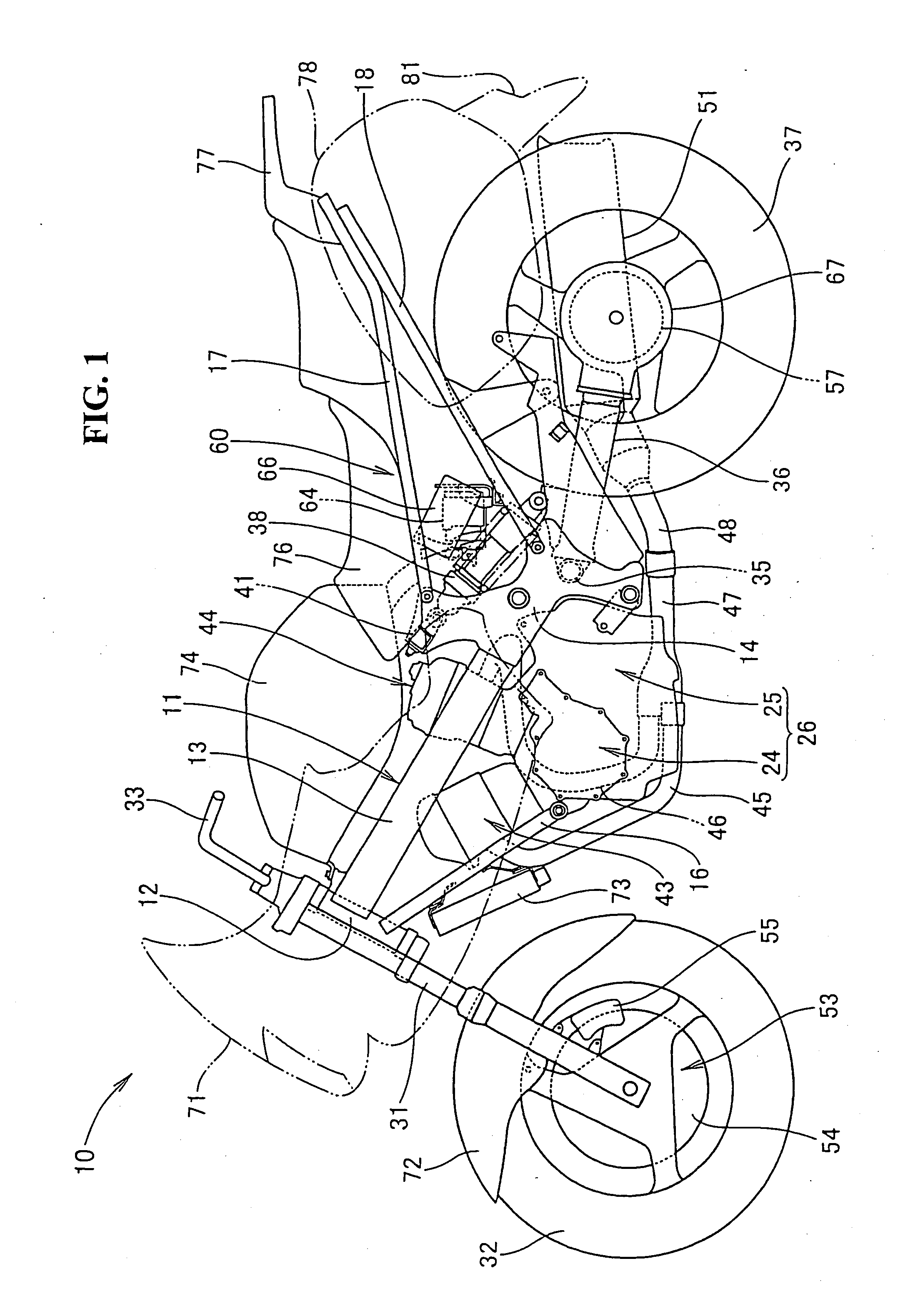
[0064] Referring to accompanied drawings, a best mode for carrying out the present invention will be described below. The drawings are to be viewed in the orientation in which the reference numerals are viewed in the correct way.

[0065]FIG. 1 is a side view of a motorcycle in which a swing arm supporting structure according to the present invention is applied. A motorcycle 10 includes a vehicle body frame 11 including a head pipe 12, a pair of left and right main frames 13, 13 (only the reference numeral 13 on the near side is shown) extending from the head pipe 12 rearwardly and obliquely downwardly with a pair of left and right plate members 14, 15 (only the reference numeral 14 on the near side is shown) being mounted to rear ends of the main frames 13, 13. A pair of left and right down frames 16, 16 (only the reference numeral 16 on the near side is shown) are provided that extend from the head pipe 12 rearwardly and obliquely downwardly below the main frames 13, 13 with a pair ...


PUM


Abstract

To restrain an increase in the numbers of components and process steps and achieve an easy mounting and dismounting of a pivot shaft. An arm supporting member includes a pair of left and right plate members, a middle cross pipe extending between the plate members and a center pivot plate mounted to the middle cross pipe. A pivot shaft is supported by the plate member and the center pivot plate, and a drive shaft is arranged between the plate member and the center pivot plate. The middle cross pipe is arranged above the pivot shaft on a front portion of a vehicle. The center pivot plate is provided with an upright wall as a receiving portion for aiding the positioning of the bearing member by receiving the bearing member, more specifically, the collar when assembling the swing arm to the center pivot plate and the plate member.

Description

CROSS-REFERENCE TO RELATED APPLICATIONS [0001] The present application claims priority under 35 USC 119 to Japanese Patent Application No. 2005-004151 filed on Jan. 11, 2005 and Japanese Patent Application No. 2005-013921 filed on Jan. 21, 2005 the entire contents of which are hereby incorporated by reference. FIELD OF THE INVENTION [0002] The present invention relates to an improved swing arm supporting structure for a motorcycle. DESCRIPTION OF BACKGROUND ART [0003] A swing arm supporting structure for a motorcycle is known wherein a pivot shaft for mounting a rear arm as a swing arm to a rear portion of a vehicle frame is arranged on a side of a drive shaft for transmitting power to a rear wheel. See, for example, JP-A-2002-87364. [0004] FIG. 3 and FIG. 4 in JP-A-2002-87364 will be described below. Reference numerals used hereinafter are the same reference numerals as set forth in JP-A-2002-87364. [0005] FIG. 4 in JP-A-2002-87364 illustrates a state wherein rear arm brackets 7 ar...

Claims


Application Information

Patent Timeline
Patent Type & Authority Applications(United States)
IPC IPC(8): B62M7/00
CPCB62K25/283B62M17/00
Inventor MISAKI, KENICHIISHIKAWA, YUZURUTAKAHASHI, ATSUHIKOKADOTA, MASAKAZUTAKASAKI, ATSUSHI
Owner HONDA MOTOR CO LTD
Why Eureka
Try Eureka