Methods and Apparatus for Self-Starting Dimmable Ballasts With A High Power Factor

a dimmable ballast, high-power technology, applied in the direction of electric variable regulation, process and machine control, instruments, etc., can solve the problems of increasing the cost of ballasts, poor efficiency of ballast circuits, and poor efficiency of power factor correction circuits, so as to achieve high power factor and poor efficiency. , the effect of high power factor

Inactive Publication Date: 2009-08-13
PURESPECTRUM
View PDF99 Cites 6 Cited by
  • Summary
  • Abstract
  • Description
  • Claims
  • Application Information

AI Technical Summary

Benefits of technology

[0003]Methods and apparatus for self-starting, dimmable ballast circuits are disclosed. A self-starting dimmable ballast circuit in accordance with one or more embodiments of the invention includes a power source coupled to a first node and a second node, the power source having a current that alternates at a line frequency and a first voltage. The first node and the second node are coupled to each other via an energy storage device that stores energy at a first frequency that exceeds the line frequency of the power source. A first switch is operable to selectively couple the energy storage device to a resonant circuit via the first node. The resonant circuit has a resonant frequency and stores energy during a first portion of a cycle of the first frequency. A second switch is operable to selectively couple the energy storage device to a resonant circuit via the second node to cause energy stored in the resonant circuit to be substantially stored in the energy storage device during a second portion of the cycle of the first frequency. In addition, the resonant circuit is selectively operable to increase the first voltage to a higher second voltage during a first portion of a cycle of the line frequency.
[0004]In the field of light sources (e.g., gas discharge lamps, fluorescent lamps, light emitting diodes, etc.), the light sources generally present a negative resistance that causes the power source to increase the amount of electrical current provided. To limit the current, a ballast circuit is typically provided that limits the amount of current provided to the light source. FIG. 1 illustrates a conventional ballast circuit with a high power factor and includes a high power factor correction circuit. However, such power factor correction circuits generally have poor efficiency caused by losses due to a power transistor and a power diode and increases costs of the ballasts due to additional circuitry required. As a result, such ballast circuits typically have poor efficiency and increase the number of components used in a conventional power factor correction ballast. Further, such ballast circuits generally include a large, high voltage, low temperature electrolytic capacitor that substantially limits its corresponding lifespan and temperature rating.

Problems solved by technology

However, such power factor correction circuits generally have poor efficiency caused by losses due to a power transistor and a power diode and increases costs of the ballasts due to additional circuitry required.
As a result, such ballast circuits typically have poor efficiency and increase the number of components used in a conventional power factor correction ballast.
Further, such ballast circuits generally include a large, high voltage, low temperature electrolytic capacitor that substantially limits its corresponding lifespan and temperature rating.

Method used


Image

  • Methods and Apparatus for Self-Starting Dimmable Ballasts With A High Power Factor
  • Methods and Apparatus for Self-Starting Dimmable Ballasts With A High Power Factor
  • Methods and Apparatus for Self-Starting Dimmable Ballasts With A High Power Factor

Examples


Embodiment Construction

[0015]Methods and apparatus for self-starting dimmable ballasts with a high power factor are described herein. In the described examples, a self-starting dimmable ballast circuit having a high power factor directly interfaces a power source with a light source (e.g., with or without filaments) via a single resonant circuit. In addition, the described dimmable ballasts include a high frequency bypass capacitor to recycle high frequency energy during its operation to increase efficiency. Further, coupled inductors are implemented into a loop to boost a voltage and start the operation of the light source without requiring a separate starter circuit. Due to the operation of the high frequency bypass capacitor and the inductors in the loop, the described examples achieve a high power factor (e.g., 0.7-0.99) and a high efficiency (90-99%).

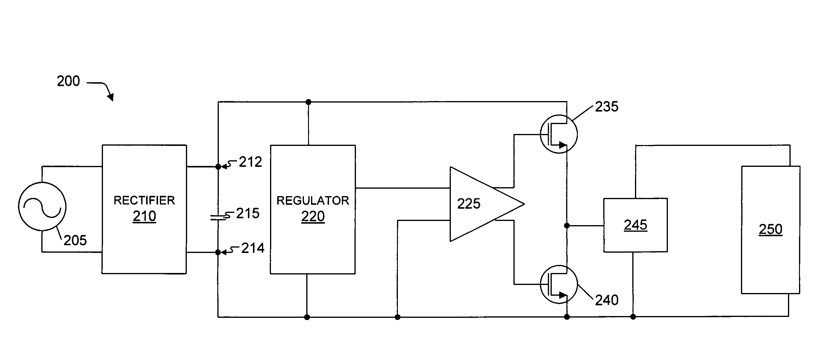
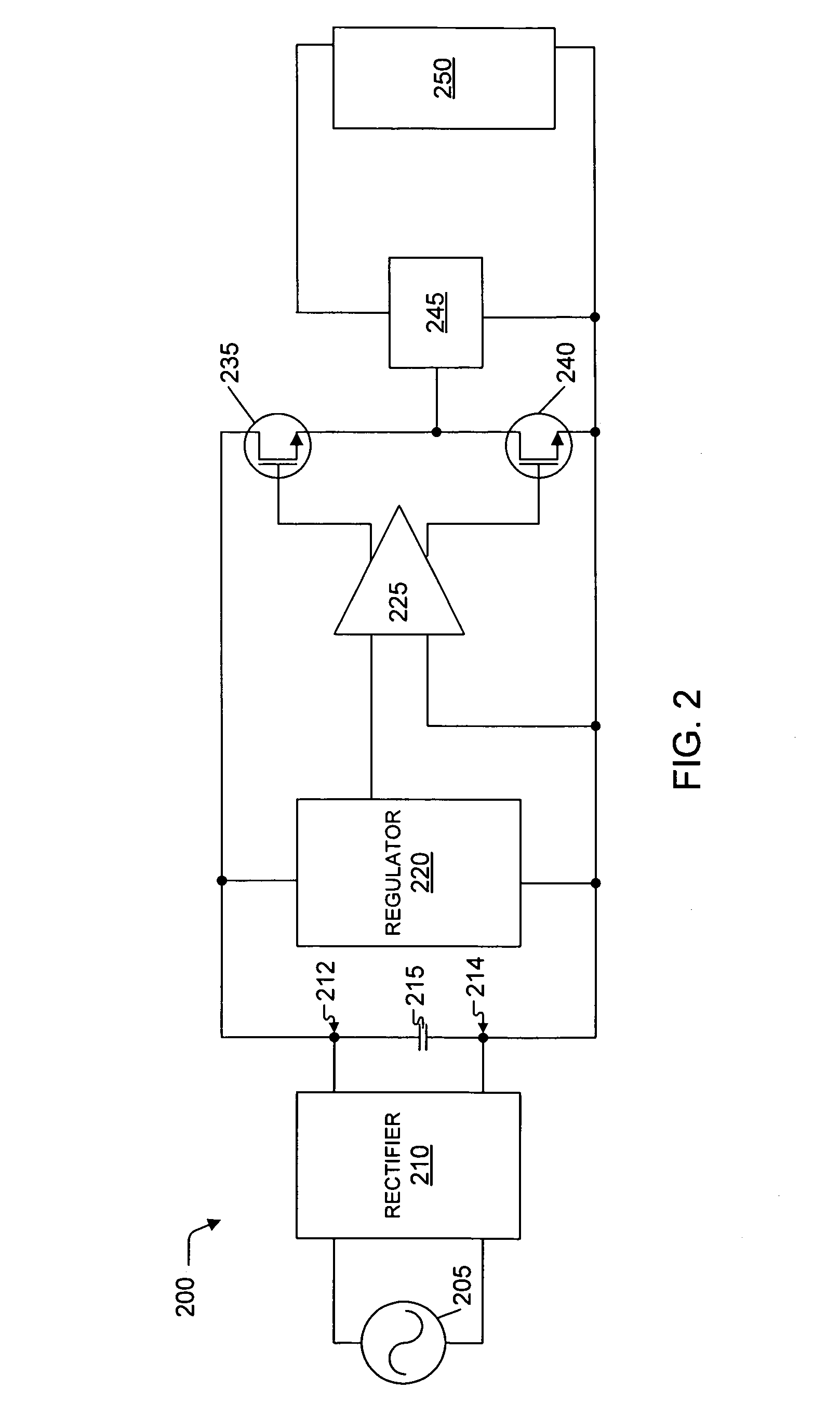
[0016]FIG. 2 illustrates a block diagram of an example ballast circuit 200 configured to have a high power factor and high efficiency. Typically, circui...


PUM


Abstract

Methods and apparatus for self-starting dimmable ballast circuits are disclosed. In the described examples, a dimmable ballast circuit includes a rectifier, an energy storage device, a driver circuit, and a resonant circuit that are configured to actuate the light source such as a fluorescent lamp. The power source is coupled to the light source via a single resonant circuit that includes power factor correction therein. Further, the resonant circuit is selectively configured to start the light source without requiring a separate starter circuit. Further, energy storage device is a capacitor that stores high frequency energy and continually recycles energy in the circuit, resulting in a circuit with a large power factor. Because the current flowing in the circuit is substantially sinusoidal, the described examples generally have an ideal power factor.

Description

RELATED APPLICATIONS[0001]This application claims the benefit under 35 U.S.C. §120 as a continuation-in-part of U.S. Patent Application entitled “Methods and Apparatus for Dimmable Ballasts with a High Power Factor” filed on Jul. 23, 2008, bearing Ser. No. 12 / 178,397, which further claims the benefit under 35 U.S.C. §119(e) to U.S. Provisional Patent Application entitled “Dimmable Ballast with High Power Factor” filed on Feb. 8, 2008, bearing Ser. No. 61 / 006,965. Both of the patent applications are herein incorporated by reference for all that they teach.FIELD OF THE DISCLOSURE[0002]The present disclosure relates generally to electronic lighting ballasts and, more particularly, to methods and apparatus for self-starting dimmable ballasts with high a power factor.SUMMARY OF THE INVENTION[0003]Methods and apparatus for self-starting, dimmable ballast circuits are disclosed. A self-starting dimmable ballast circuit in accordance with one or more embodiments of the invention includes a ...

Claims


Application Information

Patent Timeline
Patent Type & Authority Applications(United States)
IPC IPC(8): H05B41/36
CPCY02B20/185H05B41/2828Y02B20/00
Inventor KING, RAY J.
Owner PURESPECTRUM
Why Eureka
Try Eureka