Electromagnetic flowmeter

a flowmeter and electromagnetic technology, applied in the direction of electromagnetic flowmeters, volume/mass flow, measurement devices, etc., can solve the problems of increasing manufacturing costs, difficult to manufacture high-precision measurement conduits, complicated cross-sectional elliptical shapes, etc., to suppress magnetic losses, low power, and large signal

Active Publication Date: 2014-10-09
SMC CORP
View PDF0 Cites 6 Cited by
  • Summary
  • Abstract
  • Description
  • Claims
  • Application Information

AI Technical Summary

Benefits of technology

[0014]According to the present invention, in the electromagnetic flowmeter in which the measurement conduit made from a resin material is disposed in the body, and pairs of coils and electrodes are arranged in confronting relation, respectively, on the outer circumferential side of the measurement conduit, one end portion and another end portion of the measurement conduit are connected respectively to the upstream side port and the downstream side port in the body. The one end portion and the other end portion are formed respectively with true circular shapes in cross section, whereas the intermediate portion between the one end portion and the other end portion is formed with an oval shape in cross section. In addition, on the measurement conduit, the coils are arranged in

Problems solved by technology

However, for example, when the lining is formed by adhesion of a resin material to the inner circumferential surface of the measurement conduit, creation of the cross-sectional elliptical shape is complicated, and it is difficult to manufacture the measurement cond

Method used


Image

  • Electromagnetic flowmeter
  • Electromagnetic flowmeter
  • Electromagnetic flowmeter

Examples


Embodiment Construction

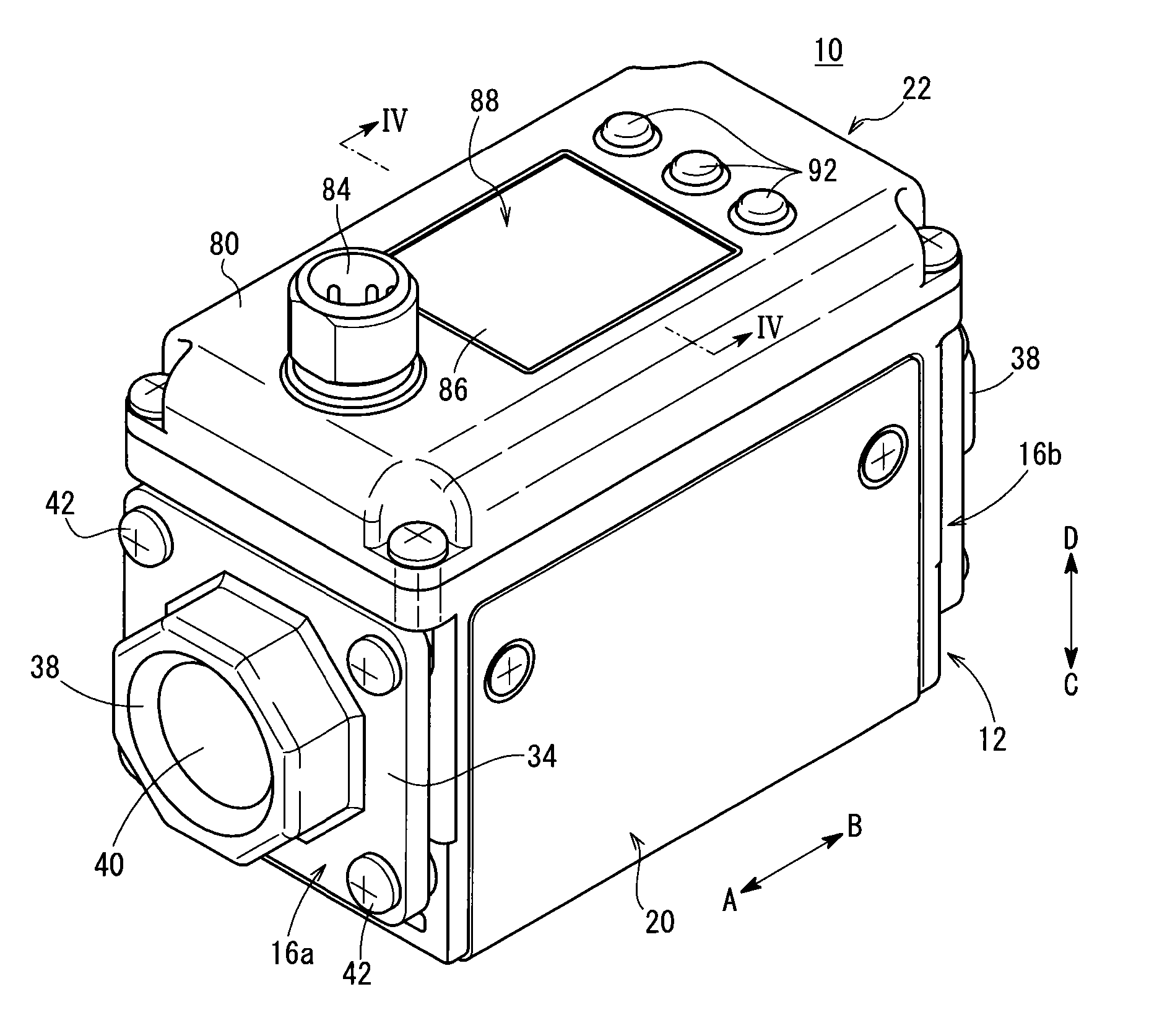
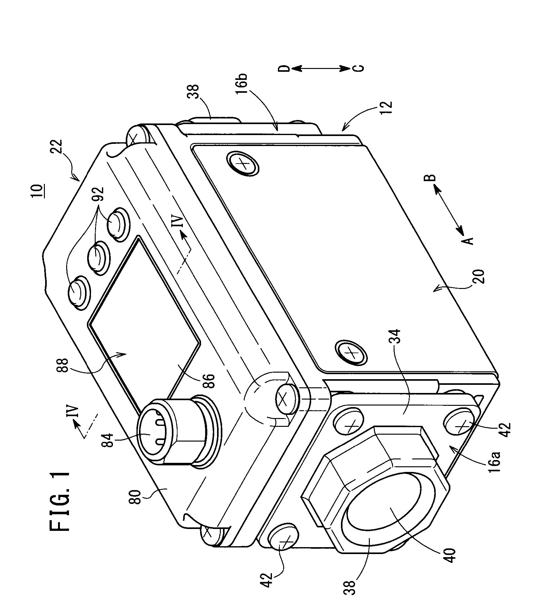
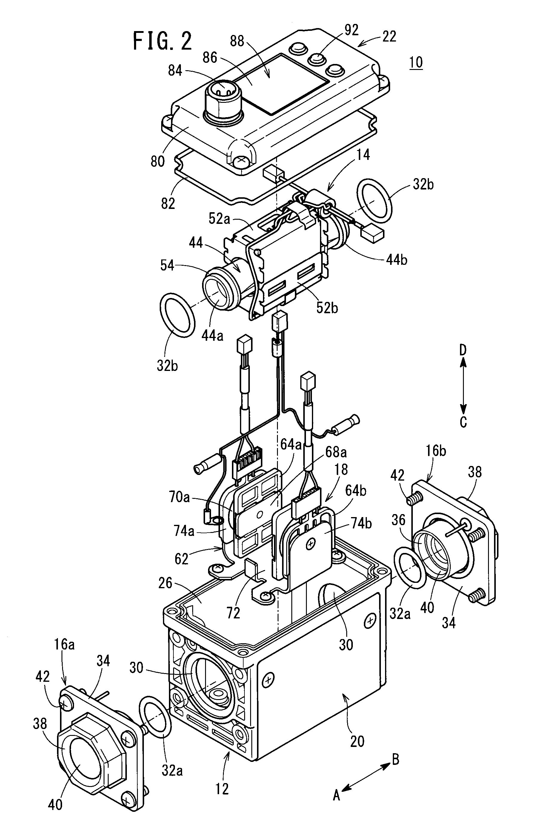
[0020]As shown in FIGS. 1 through 4, an electromagnetic flowmeter 10 includes a body 12, a pipe unit 14 accommodated in the interior of the body 12, a pair of (ground potential) attachments 16a, 16b connected to opposite ends of the body 12 and the pipe unit 14, a solenoid unit 18 disposed on both sides of the pipe unit 14 in the interior of the body 12, a cover member 20 that covers side surfaces of the body 12, and a display unit 22 provided on an upper surface of the body 12.

[0021]The body 12 is formed, for example, from a metal material with a substantially rectangular shape in cross section, and is formed in a hollow shape having a space in the interior thereof. Installation holes 24, in which the attachments 16a, 16b are mounted, open respectively on opposite ends in the axial direction (the direction of arrows A and B) of the body 12. An opening 26, in which the display unit 22 is mounted, is provided on the upper surface of the body 12. The cover member 20, which is U-shaped...


PUM


Abstract

An electromagnetic flowmeter includes a yoke of a solenoid unit, which is accommodated in the interior of a body. The yoke is U-shaped in cross section, with a pipe unit including a measurement conduit being arranged in the interior of the yoke. One end portion and another end portion of the measurement conduit are formed with true circular shapes in cross section, whereas an intermediate portion thereof between the one end portion and the other end portion is formed with an oval shape in cross section. On the measurement conduit, cross-sectional straight line portions thereof, which are formed in the intermediate portion, are arranged in a vertical direction. Coils of the solenoid unit and excitation plates are arranged in facing relation to the cross-sectional straight line portions.

Description

CROSS-REFERENCE TO RELATED APPLICATION[0001]This application is based upon and claims the benefit of priority from Japanese Patent Application No. 2013-080264 filed on Apr. 8, 2013, the contents of which are incorporated herein by reference.BACKGROUND OF THE INVENTION[0002]1. Field of the Invention[0003]The present invention relates to an electromagnetic flowmeter which is capable of measuring the flow rate of a fluid that flows in the interior of a flow passage.[0004]2. Description of the Related Art[0005]Heretofore, for example, an electromagnetic flowmeter has been known in which, by energizing coils, a magnetic field is formed in a flow passage through which a fluid flows, and the flow rate of the fluid is calculated based on an electromotive force generated in accordance with the conductivity of the fluid that flows through the flow passage.[0006]Such a flowmeter, for example as disclosed in Japanese Patent No. 4591015 (Patent Document 1), is equipped with a measurement conduit...

Claims


Application Information

Patent Timeline
IPC IPC(8): G01F1/58
CPCG01F1/588G01F15/14G01F15/18
Inventor FUKANO, YOSHIHIROTSUDA, YUJI
Owner SMC CORP
Why Eureka
Try Eureka