Actuator unit having two actuator pins

a technology of actuator pins and actuators, which is applied in the direction of non-mechanical valves, valve details, electrical devices, etc., and can solve problems such as a large constructive spa

Inactive Publication Date: 2013-01-03
SCHAEFFLER TECH AG & CO KG
View PDF1 Cites 8 Cited by
  • Summary
  • Abstract
  • Description
  • Claims
  • Application Information

AI Technical Summary

Benefits of technology

[0004]The object of the present invention is therefore to improve an actuator unit for internal combustion piston engines

Problems solved by technology

The offsetting of the two control needles relative to the mid-axis of the electromagnet unit results in a suboptimal utilization of the magnetic

Method used


Image

  • Actuator unit having two actuator pins
  • Actuator unit having two actuator pins

Examples


Embodiment Construction

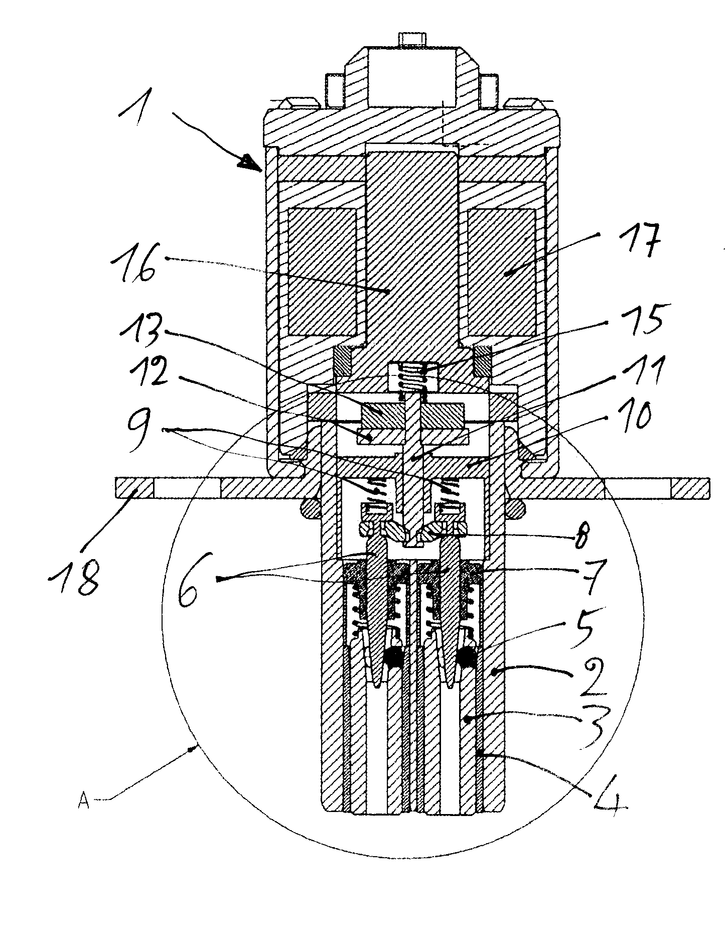
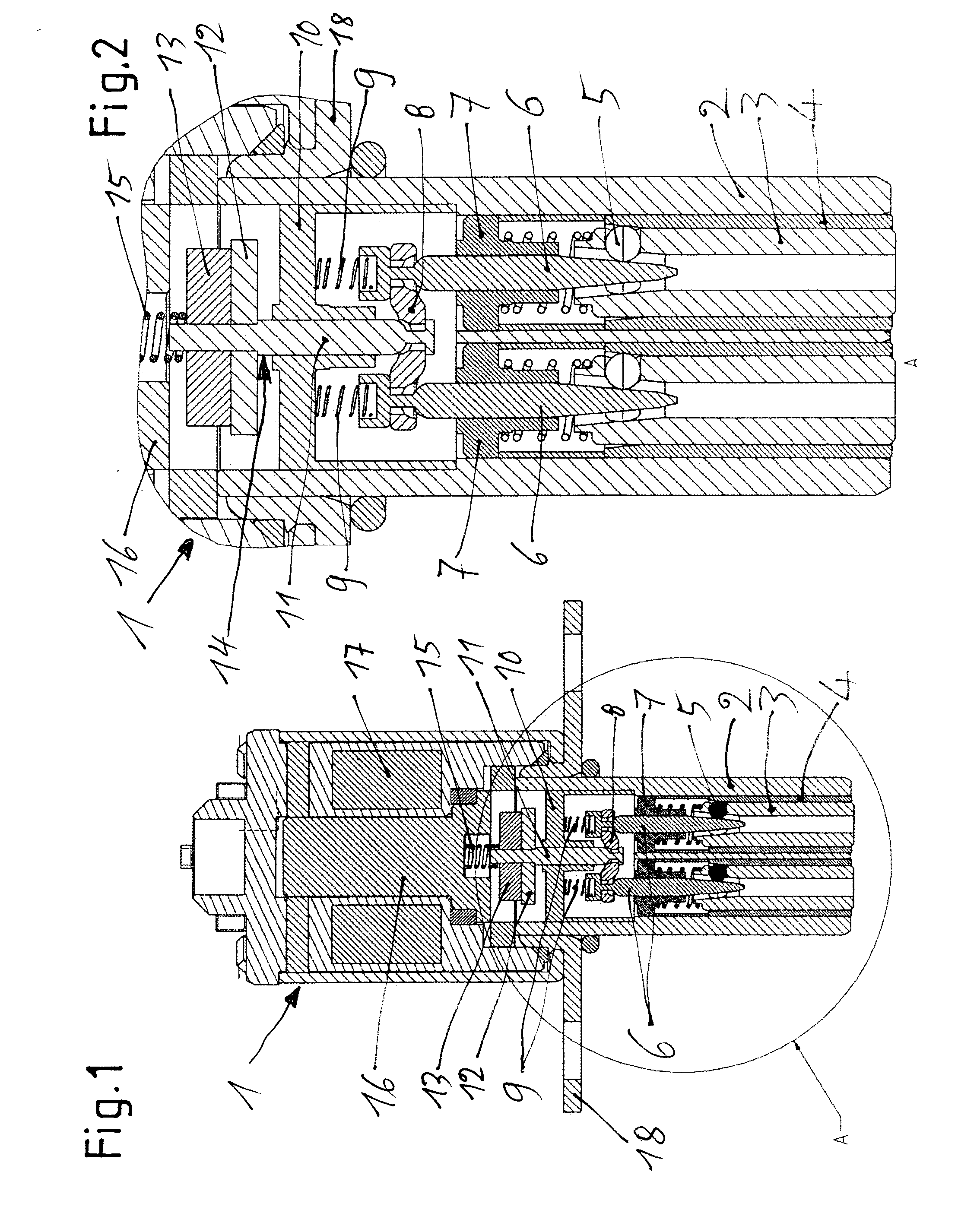
[0012]In FIGS. 1 and 2, insofar as the parts are shown individually, 1 generally designates an actuator unit having a guide sleeve 2 in which actuator pins 3 are mounted so as to be axially movable. In the guide sleeve 2, bearing sleeves 4 are placed that are widened at their upper, inner end. At the level of the widening, the actuator pins 3 have clamping bodies 5, fashioned as balls, that are displaceably held in radial openings of the actuator pins 3. The clamping bodies 5 stand in operative connection with control needles 6, which have a conical construction and which, by displacement, cause a radial movement of the clamping bodies 5 outward, or release these bodies. In this way, in the upper end position of the actuator pins 3 there takes place an arrestable locking of the actuator pins. The actuator pins 3 are loaded by pressure springs that are supported in bearings 7 that simultaneously take over the guiding of the control needles 6. If the arresting of the clamping bodies 5...


PUM

PropertyMeasurementUnit
Circumferenceaaaaaaaaaa

Abstract

An internal combustion piston engine having gas exchange valves actuated by cams of a camshaft. The cams are sliding cams having two cams per sliding cam unit situated on a basic shaft in rotationally fixed fashion but axially displaceable. At least one actuator unit has two actuator pins for displacing the sliding cam units into different axial positions using displacement grooves on the circumference of the sliding cam units, the grooves being helical and situated mirror-symmetrically, and having an ejection ramp for the actuator pins. The actuator pins are spring-loaded toward the sliding cam unit and, in retracted positions, can be fixed by arresting devices, which have control needles that correspond to clamping bodies of locking devices. These needles are actuatable by an electromagnet unit, with the control needles being connected with a needle bridge. A pin engages the needle bridge, and the pin is controlled by the electromagnet unit.

Description

CROSS-REFERENCE TO RELATED APPLICATIONS[0001]This application claims the benefit of German Patent Application No. 102011078154.4, filed Jun. 28, 2011, which is incorporated herein by reference as if fully set forth.FIELD OF THE INVENTION[0002]An internal combustion piston engine having a crank drive, having at least one cylinder head whose inlet and outlet channels are each governed by at least one gas exchange valve, formed as intake and exhaust valves, which valves are capable of being actuated by cams of at least one camshaft and by transmitting elements driven by the cams, with the cams being fashioned as sliding cams having at least two cams per sliding cam unit which are situated on a basic shaft in rotationally fixed fashion but so as to be capable of being displaced axially on the shaft, the basic shaft being mounted so as to be fixed relative to the internal combustion engine, and having at least one actuator unit, fixed relative to the internal combustion engine, having tw...

Claims


Application Information

Patent Timeline
IPC IPC(8): F01L1/047
CPCF01L2001/0473F01L25/08F01L2820/031Y10T29/49293H01F7/1646F01L1/047F01L13/0036F01L2013/0052
Inventor POPP, OLIVERGUNNEL, RONNY
Owner SCHAEFFLER TECH AG & CO KG
Why Eureka
Try Eureka