Eureka AIR delivers breakthrough ideas for toughest innovation challenges, trusted by R&D personnel around the world.

Magnetic resonance measurement of ultrasound properties

a magnetic resonance and ultrasound technology, applied in the field of high intensity focused ultrasound, can solve the problems of tissue effect on the phase of ultrasound between the target zone and the ultrasonic transducer, and the defocusing of the sonication poin

Active Publication Date: 2013-12-26
KONINKLIJKE PHILIPS ELECTRONICS NV
View PDF17 Cites 7 Cited by
  • Summary
  • Abstract
  • Description
  • Claims
  • Application Information

AI Technical Summary

Benefits of technology

The patent describes a method for controlling the frequency and phase of ultrasound to improve the accuracy of ultrasound imaging. The method involves using a resonant frequency modulator to control the phase of ultrasound waves relative to a magnetic field. By modulating the magnetic resonance frequency of molecules in the target area, the method allows for better imaging of the target. The method also involves using a set of directions to maximize the magnetic resonance signal, which can be determined by experiment or using a curve or model. The use of multiple ultrasound transducer elements and the calculation of control phases further enhances the accuracy of the method. Overall, this patent provides a way to improve the accuracy of ultrasound imaging by controlling the frequency and phase of ultrasound waves.

Problems solved by technology

A difficulty of performing ultrasonic therapy is that the effect of tissues on the between the target zone and the ultrasonic transducer on the phase of the ultrasound may not be known.
This may cause a defocusing of the sonication point or even a shift in the location of the sonication point.

Method used


Image

  • Magnetic resonance measurement of ultrasound properties
  • Magnetic resonance measurement of ultrasound properties
  • Magnetic resonance measurement of ultrasound properties

Examples


Embodiment Construction

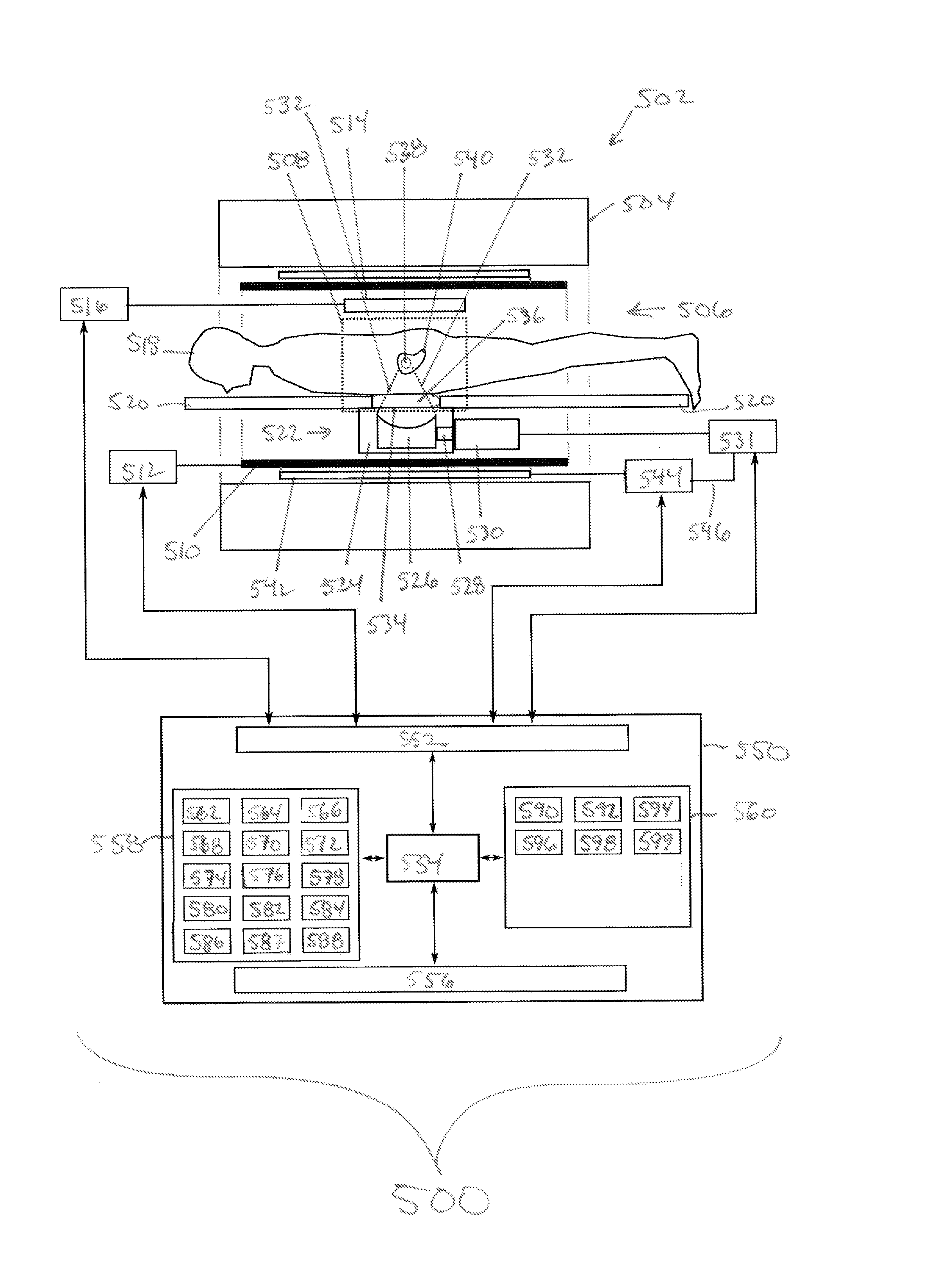
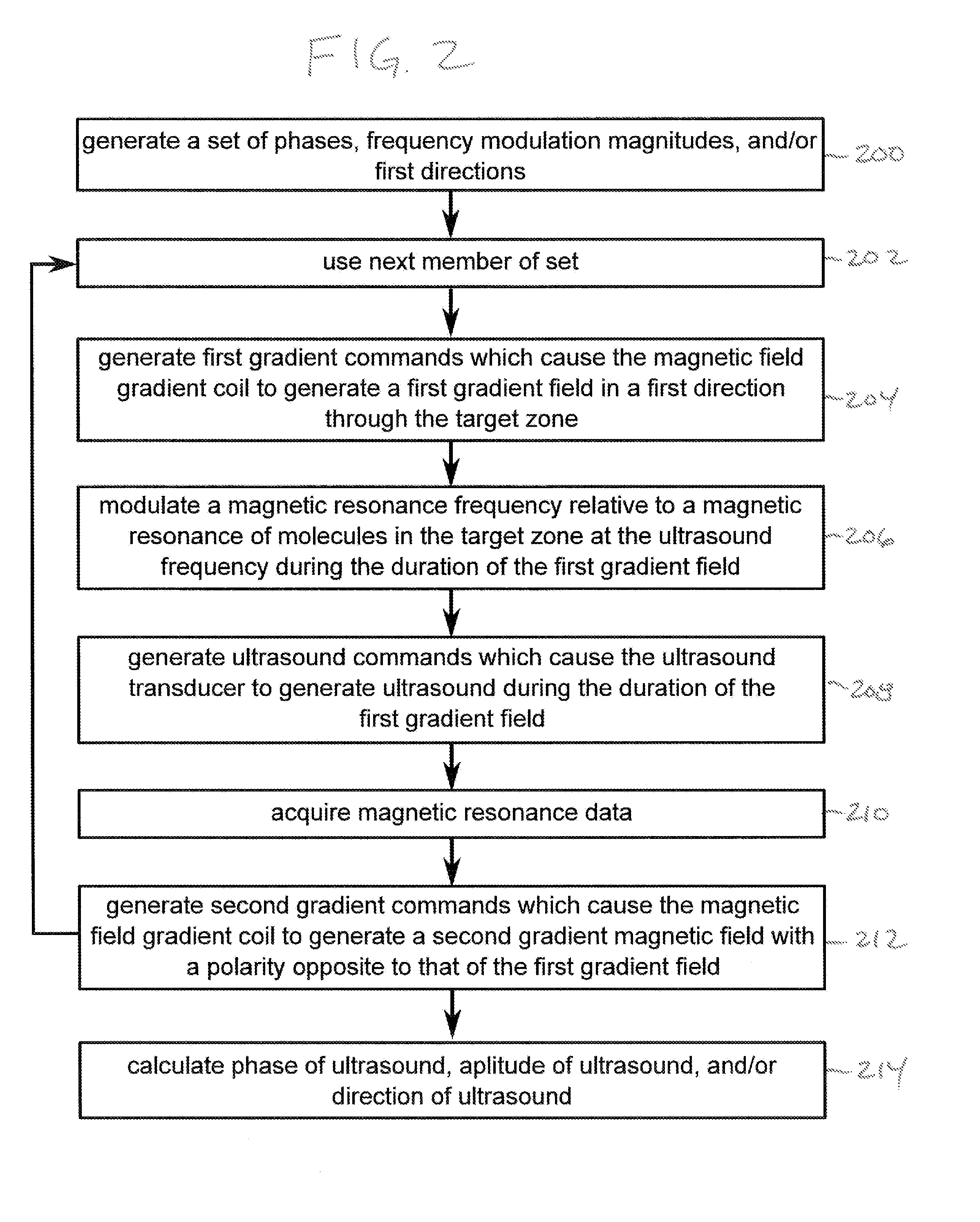
[0067]Like numbered elements in these figures are either equivalent elements or perform the same function. Elements which have been discussed previously will not necessarily be discussed in later figures if the function is equivalent.

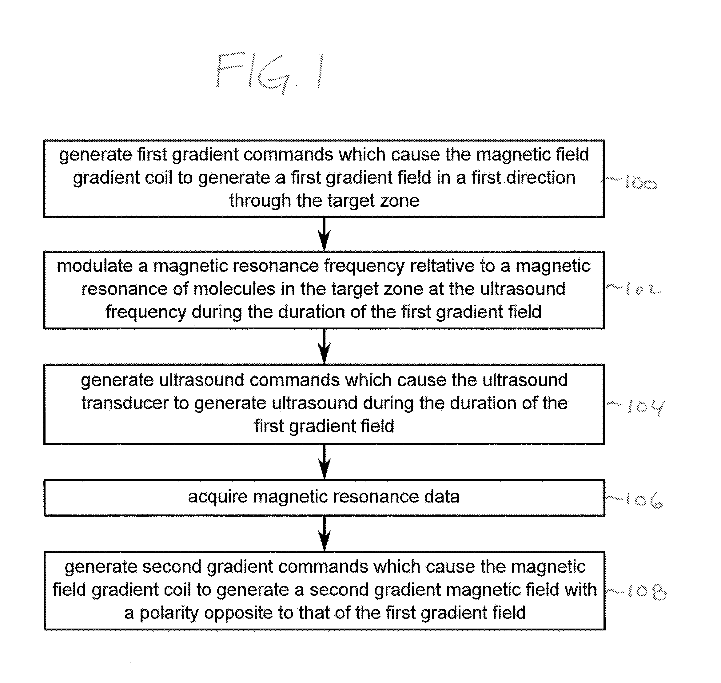
[0068]FIG. 1 shows a flow diagram which illustrates a method according to an embodiment of the invention. In step 100 first gradient commands are generated which cause the magnetic field gradient coil to generate a first gradient field in a first direction through the target zone. Next in step 102 a magnetic resonance frequency is modulated relative to magnetic resonance molecules in the target zone at the ultrasound frequency during the duration of the first gradient. Next in step 104 ultrasound commands are generated which cause the ultrasound transducer to generate ultrasound during the duration of the first gradient field. In step 106 magnetic resonance data acquisition starts from a magnetic resonance imaging system. Finally in step 108 second grad...


PUM


Abstract

An apparatus (500, 600) comprising an ultrasound transducer element (300) for generating an ultrasonic beam (302) through a target zone (308, 538). The ultrasonic beam has an ultrasound frequency. The apparatus comprises a magnetic resonance system (502) with a resonant frequency modulator (542, 544, 516) for modulating a magnetic resonance frequency relative to a magnetic resonance of molecules in the target zone at the ultrasound frequency. Instructions cause a processor to repeatedly generate (100, 204) first gradient commands (562) which cause a magnetic field gradient coil to generate a first gradient magnetic field (710, 810) through the target zone. The gradient magnetic field has field lines directed in a first direction (304). The processor repeatedly modulates (102, 206) the magnetic resonance frequency at the ultrasound frequency, generates (104, 208) ultrasound commands (566), acquires (106, 210) magnetic resonance data from the target zone, and generates (108, 212) second gradient commands (564).

Description

TECHNICAL FIELD[0001]The invention relates to high intensity focused ultrasound, in particular to magnetic resonance guided high intensity focused ultrasound.BACKGROUND OF THE INVENTION[0002]Ultrasound from a focused ultrasonic transducer can be used to selectively treat regions within the interior of the body. Ultrasonic waves are transmitted as high energy mechanical vibrations. These vibrations induce tissue heating as they are damped, and they can also lead to cavitation. Both tissue heating and cavitation can be used to destroy tissue in a clinical setting. However, heating tissue with ultrasound is easier to control than cavitation. Ultrasonic treatments can be used to ablate tissue and to kill regions of cancer cells selectively. This technique has been applied to the treatment of uterine fibroids, and has reduced the need for hysterectomy procedures. At lower powers or in pulsed mode, ultrasound can be used to selectively deliver genetic material or medicine to a region.[000...

Claims


Application Information

Patent Timeline
IPC IPC(8): A61B5/00A61N7/00A61B5/055
CPCA61B5/4836A61B5/055A61N7/00A61N7/02A61N2007/0091A61N2007/0095A61B2090/374A61B5/0036G01R33/4808G01R33/56358
Inventor VAHALA, ERKKI TAPANI
Owner KONINKLIJKE PHILIPS ELECTRONICS NV
Why Eureka
Eureka Blog
Learn More