Amplitude combining method for phase locking fiber lasers

a phase locking fiber and amplitude combining technology, applied in the direction of laser details, electrical equipment, wave amplification devices, etc., can solve the problem of limited power available from a single-mode optical fiber, and achieve the effect of maximizing the polarization of n amplifier signals and maximizing the combined power outpu

Inactive Publication Date: 2013-10-01
THE UNITED STATES OF AMERICA AS REPRESETNED BY THE SEC OF THE AIR FORCE
View PDF3 Cites 9 Cited by
  • Summary
  • Abstract
  • Description
  • Claims
  • Application Information

AI Technical Summary

Benefits of technology

[0009]A further embodiment maximizes the polarizations of the N amplifier signals in a similar manner and when combined with the phase adjuster process, maximizes the combined power output.

Problems solved by technology

The intensity and, hence, the power available from a single-mode optical fiber is limited by either optical surface damage or nonlinear optical effects.

Method used


Image

  • Amplitude combining method for phase locking fiber lasers
  • Amplitude combining method for phase locking fiber lasers
  • Amplitude combining method for phase locking fiber lasers

Examples


Embodiment Construction

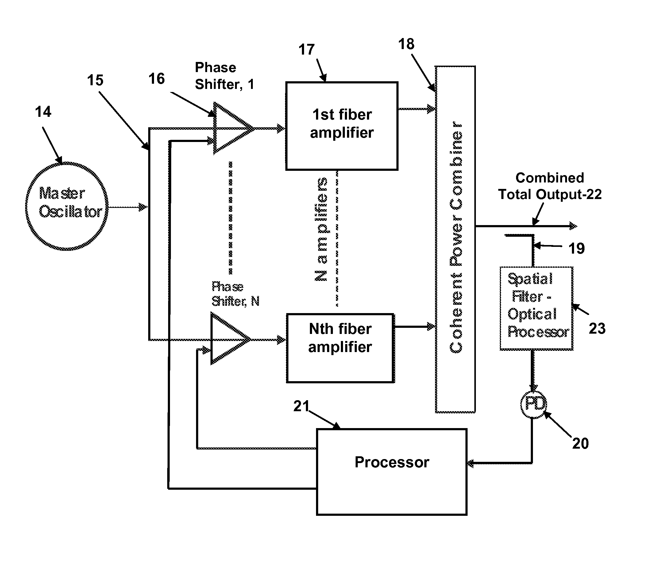
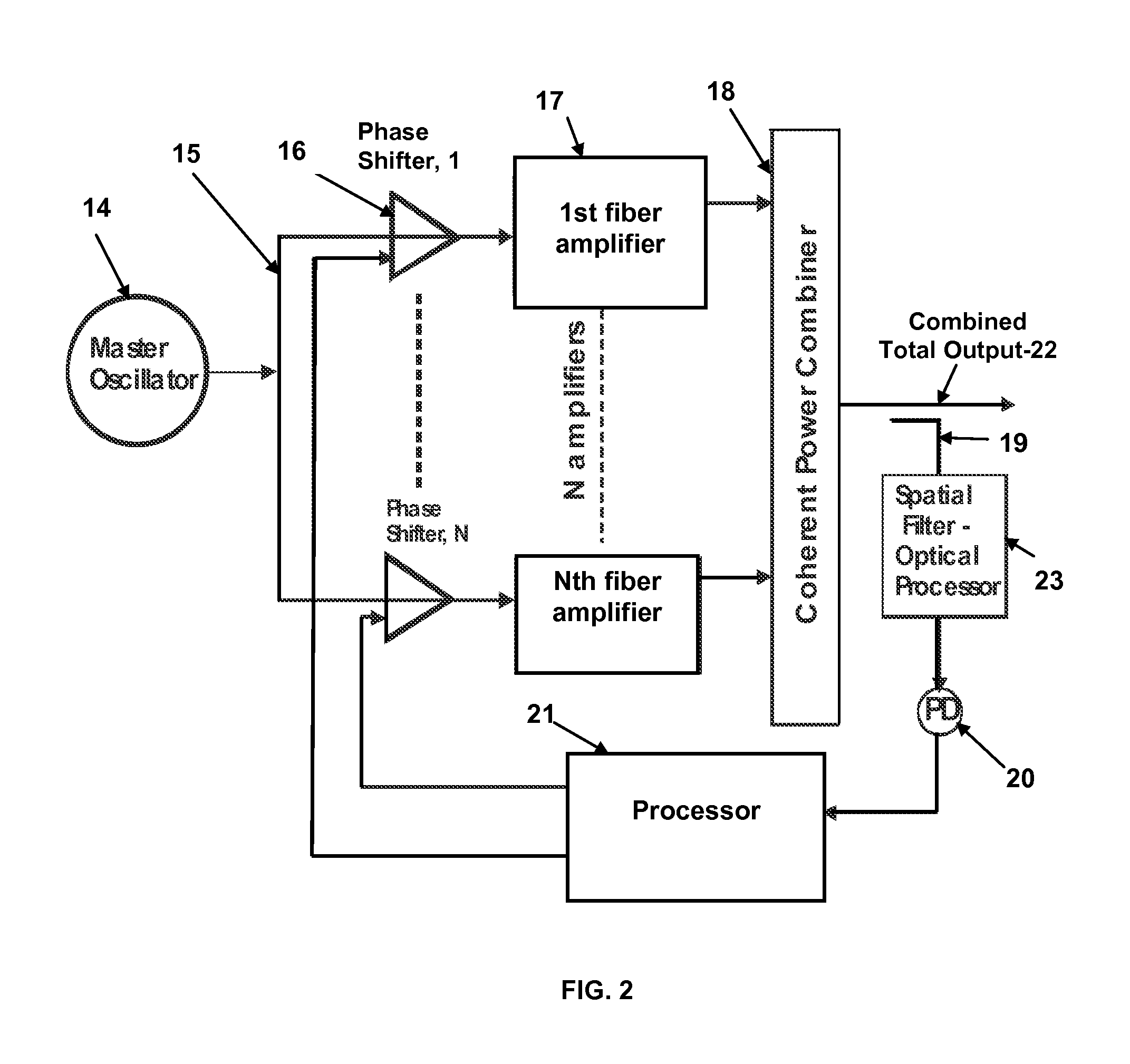
[0014]Amplitude combining for phase locking fiber lasers is a simple method for coherently combining optical fiber or other types of amplifiers. See FIG. 2 in which an array of N fiber amplifiers 17, are driven by a common stable master oscillator 14. A branch power divider 15 feeds each array amplifier 17 through an adjustable phase shifter 16. The outputs of the array of N amplifiers are optically combined by a coherent power combiner 18 and a sample is split off 19, spatially optically processed 23, and sent to a photodetector 20. The optical processor 23 is a lens arrangement that focuses a far field spot on the photodetector 20, such that the power in the central spot consists of contributions from every fiber amplifier element. The output of the photodetector 20 is a signal proportional to the power in the combined array output 22. This signal is fed to a processor 21 and it is a measure of the level of the combined output power of the N amplifiers. These amplifiers initially ...


PUM


Abstract

A method for implementing a coherent laser beam combining system in which a master laser oscillator output is split into N signals, fed through N phase adjusters and N amplifiers and combined in a coherent power combiner. The output of the combiner is sampled and sent to a processor. The processor selects one of the N phase adjusters, sweeps the phase in small steps over a 2π range, and locks the phase of that adjuster to the phase that corresponds to the maximum value of the combiner sample for that sweep cycle. The process is repeated for all the remaining phase adjusters resulting in maximizing the combiner output. The sweep cycles are repeated continuously to correct any phase errors that may occur over time. A similar method can be used in which both the polarizations and the phases of the N signals are maximized to thereby maximize the output of the coherent power combiner.

Description

STATEMENT OF GOVERNMENT INTEREST[0001]The conditions under which this invention was made are such as to entitle the Government of the United States under paragraph 1(a) of Executive Order 10096, as represented by the Secretary of the Air Force, to the entire right, title and interest therein, including foreign rights.BACKGROUND OF THE INVENTION[0002]The invention relates generally to a method for phase locking and coherently combining multiple laser amplifiers, and in particular to sweeping amplifier phase modulators in small steps over a 2π range sequentially and selecting the phase of each that maximizes the combined output.[0003]The intensity and, hence, the power available from a single-mode optical fiber is limited by either optical surface damage or nonlinear optical effects. These limitations can be overcome by coherent beam-combining of the output power from multiple optical fibers. Fine control of the optical phase is required for any multi-fiber approach.[0004]The most rel...

Claims


Application Information

Patent Timeline
Patent Type & Authority Patents(United States)
IPC IPC(8): H01S3/13
CPCH01S3/06754H01S3/1307H01S3/2383
Inventor O'LOUGHLIN, JAMES P.HEGGEMEIER, JEFFRY P.HAMIL, ROY A.
Owner THE UNITED STATES OF AMERICA AS REPRESETNED BY THE SEC OF THE AIR FORCE
Why Eureka
Try Eureka