Method and system for scanning apertureless fluorescence mircroscope

a fluorescence mircroscope and apertureless technology, applied in the field of high resolution microscopy techniques, can solve the problems of limited resolution ability of such far field optical microscopy, subwavelength aperture techniques that create other limitations, and may still exist certain practical limitations, etc., to achieve the effect of improving resolution, narrow transmission width and convenient us

Inactive Publication Date: 2007-07-24
CALIFORNIA INST OF TECH
View PDF8 Cites 8 Cited by
  • Summary
  • Abstract
  • Description
  • Claims
  • Application Information

AI Technical Summary

Benefits of technology

[0012]In a specific embodiment, the invention provides a capability to extend the lifetime of fluorescent molecules. Preferably, the method extends the life of such molecules by turning an excitation laser on only during specific periods of the data gathering cycle, which can improve and possibly maximizes a lifetime of the fluorescent molecule by delaying photobleaching or other similar features. Photobleaching is a photo-catalyzed chemical reaction that severely reduces or completely eliminates fluorescence emission. In addition this allows the signal to be maximized during imaging. Image scans often include series of fast probe movements, or line scans, along one axis and backcoupled with a slow continuous movement or discrete set of movements along the orthogonal axis of the sample surface plane-rastering pattern. Such rastering pattern continues until the desired portion of the sample plane is mapped which forms one image frame. The probe is typically made to oscillate rapidly (typically but not limited to 50-400 kilohertz oscillation frequency) up and down so that it lightly “taps” on the sample surface, following the sample topography while being rastered over the surface. When an image frame begins or ends, the probe controller sends a voltage signal that is monitored by the data acquisition computer. Similarly, the probe controller sends a voltage signal when each line scan begins in one direction and another signal at the beginning of the return movement. The image is typically constructed of either all-forward direction line scans or all return line scans in certain embodiments. If forward direction line scans are desired, then the controlling software detects the voltage pulse signaling the onset of forward scanning and in turn sends a voltage signal to an acousto-optic modulator that switches so that the excitation laser transmits into the FANSOM optical system. When the return line begins, a second voltage pulse is generated by the probe controller. As this line is not being used to create the image, the controlling computer stops sending the voltage pulse to the AOM. The AOM then switches so that the excitation laser light is no longer transmitted into the FANSOM optical system and the sample is not illuminated. This process repeats for each line with the sample being illuminated only during forward direction line scans. When the image frame is complete, the laser is commanded to switch off (in this case by stopping the voltage pulse to the AOM) until the initiation of the next image frame.
[0024]Many benefits are achieved by way of the present invention over conventional techniques. For example, the present technique provides an easy to use process that relies upon conventional technology. The invention can also provide improved resolution within a predetermined range of spatial feature sizes. Preferably, the invention can be applied to capture images from biological molecules and the like. Depending upon the embodiment, one or more of these benefits may be achieved. These and other benefits will be described in more throughout the present specification and more particularly below.

Problems solved by technology

The resolving ability of such far field optical microscopy is generally limited by the diffraction of light.
Such subwavelength aperture techniques create other limitations.
Here, physical limitations relate to a skin depth of the metal used to coat the waveguide and various scanning artifacts, which yield resolutions of 30 to 50 nanometers, most typically 50 to 100 nanometers.
Such limitations include contaminated images based upon certain artifacts of the sample topography, and may include others.
Although FANSOM appears to be promising, certain practical limitations may still exist.

Method used


Image

  • Method and system for scanning apertureless fluorescence mircroscope
  • Method and system for scanning apertureless fluorescence mircroscope
  • Method and system for scanning apertureless fluorescence mircroscope

Examples


Embodiment Construction

[0042]According to the present invention, techniques for high resolution scanning are provided. More particularly, the invention provides methods and systems for improved high resolution scanning using apertureless near field scanning microscopes that image one or more fluorescent samples with single photon excitation, which we call fluorescence ANSOM microscope. But it would be recognized that the invention has a much broader range of applicability. For example, the invention can be applied with other types of images such as Raman scattering, multiphoton imaging techniques, and others. Additionally, the samples can be from a variety of different fields such as electronics, semiconductor, organic chemistry, life sciences, biotechnology, and others.

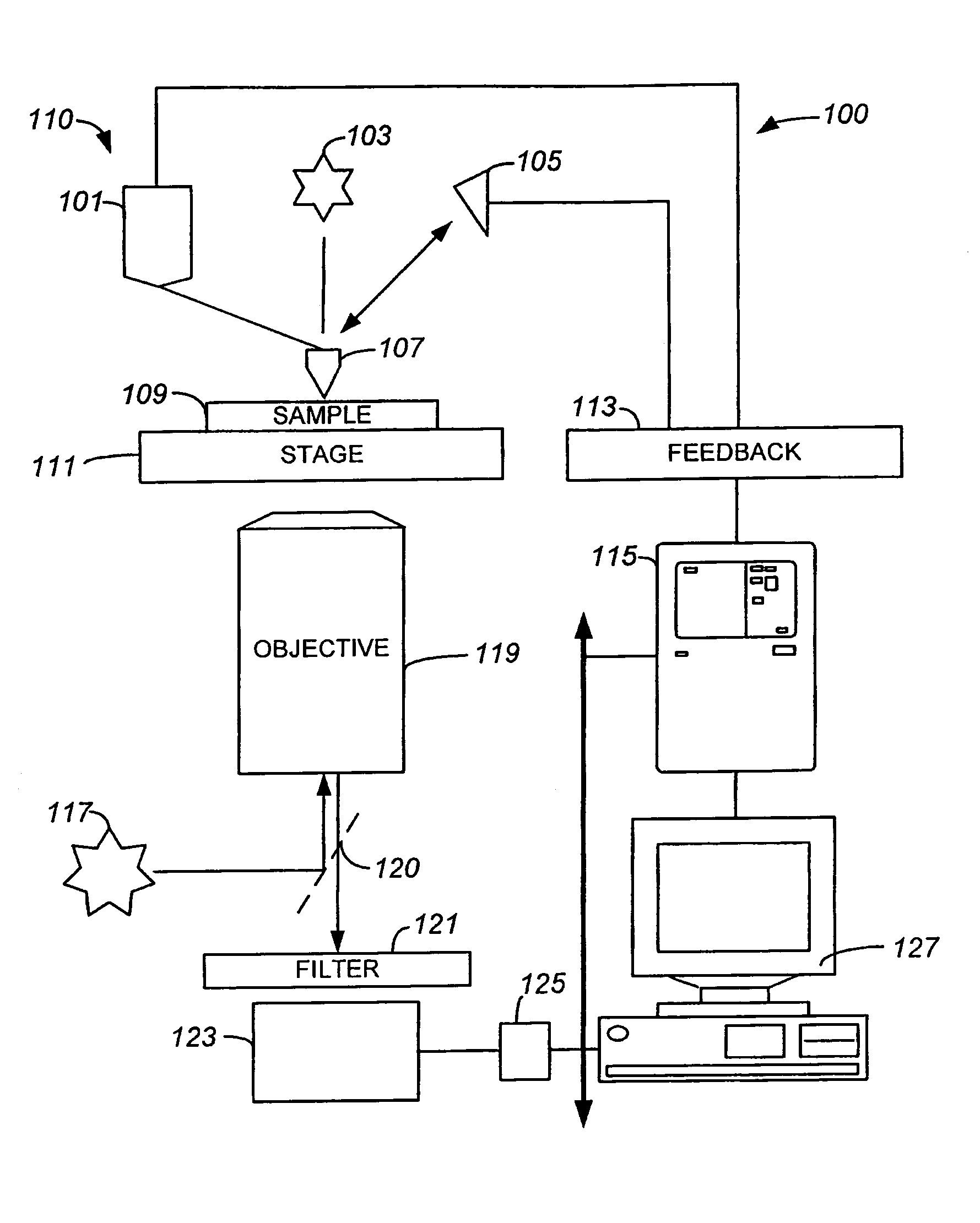
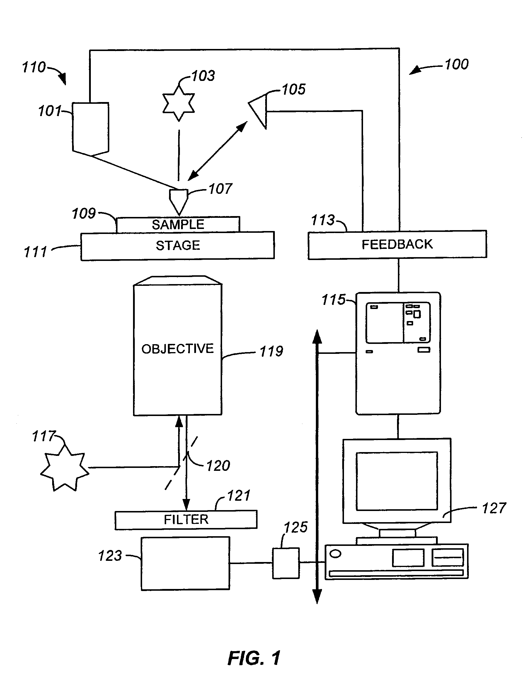
[0043]FIG. 1 is a simplified diagram of a scanning system 100 according to an embodiment of the present invention. This diagram is merely an example, which should not unduly limit the scope of the claims herein. One of ordinary skill in th...


PUM


Abstract

Methods and systems for operating an apertureless microscope for observing one or more features to a molecular sensitivity on objects are described. More particularly, the method includes moving a tip of a probe coupled to a cantilever in a vicinity of a feature of a sample, which emits one or more photons at a detected rate relative to a background rate of the sample based upon the presence of the tip of the probe in the vicinity of the feature. The method modifies the detected rate of the feature of the sample, whereupon the modifying of the detected rate causes the feature of the sample to enhance relative to background rate of the feature.

Description

STATEMENT AS TO RIGHTS TO INVENTIONS MADE UNDER FEDERALLY SPONSORED RESEARCH OR DEVELOPMENT[0001]The U.S. government has rights in the disclosed invention pursuant to National Science Foundation Grant No. DMR-0080065 to the California Institute of Technology.CROSS-REFERENCES TO RELATED APPLICATIONS[0002]This application claims priority to U.S. patent application Ser. No. 10 / 616,896, filed on Jul. 9, 2003, which claims priority to U.S. Provisional Application No. 60 / 402,351, filed Aug. 9, 2002, which are incorporated by reference herein.REFERENCE TO A “SEQUENCE LISTING,” A TABLE, OR A COMPUTER PROGRAM LISTING APPENDIX SUBMITTED ON A COMPACT DISK[0003]NOT APPLICABLEBACKGROUND OF THE INVENTION[0004]The present invention relates generally to high resolution microscopy techniques. More particularly, the invention provides methods and systems for improved high resolution scanning using apertureless near field scanning optical microscopes (“ANSOM”) that image one or more fluorescent sample...

Claims


Application Information

Patent Timeline
Patent Type & Authority Patents(United States)
IPC IPC(8): H01J3/14H01J40/14H01J5/16
CPCB82Y20/00G01Q60/20G01N21/6458B82Y35/00
Inventor QUAKE, STEPHEN R.LESSARD, GUILLAUMEWADE, LAWRENCE A.GERTON, JORDAN M.
Owner CALIFORNIA INST OF TECH
Why Eureka
Try Eureka