Analysis of a sample to determine its characteristic cycle time

a sample and cycle time technology, applied in the field of fluorescence analysis, can solve the problems of requiring a sample of many hundreds of fluorophores and high intensity illumination, requiring a comparatively long average process, and unsuitable for modern high speed processing of many measurements, so as to maximise the signal-to-noise ratio of detected signals and avoid quenching of fluorophores.

Inactive Publication Date: 2006-08-29
VICTORIA UNIVERSITY OF MANCHESTER
View PDF5 Cites 8 Cited by
  • Summary
  • Abstract
  • Description
  • Claims
  • Application Information

AI Technical Summary

Benefits of technology

[0018]The exemplary embodiment when used to measure a characteristic cycle time of a fluorophore using laser illumination, may appear superficially to resemble fluorescence correlation spectroscopy. However, there are several important differences between the invention and fluorescence correlation spectroscopy. Fluorescence correlation spectroscopy is used to determine diffusion coefficients of particles, and the detected experimental signal is caused by particles diffusing into and out of an illuminated area, the diffusion typically having a time scale of the order of milliseconds. The illumination is held at a low intensity to avoid quenching of fluorophores, and must be stabilized to a fixed intensity to avoid introducing experimental errors due to intensity fluctuations. In contrast to this the invention measures a characteristic lifetime of a sample of fluorophores by illuminating the sample at high intensity so that it cycl

Problems solved by technology

However, present methods require comparatively lengthy averaging processes, which are unsuited to modern high speed processing of many measurements (for example in high throughput screening, or imaging).
A further limitation of the above method is that it requires a sample of many hundreds of fluorophores and high intensity illumination.
A sample of the order of 100 fluorophores will not provide suff

Method used


Image

  • Analysis of a sample to determine its characteristic cycle time
  • Analysis of a sample to determine its characteristic cycle time
  • Analysis of a sample to determine its characteristic cycle time

Examples


Embodiment Construction

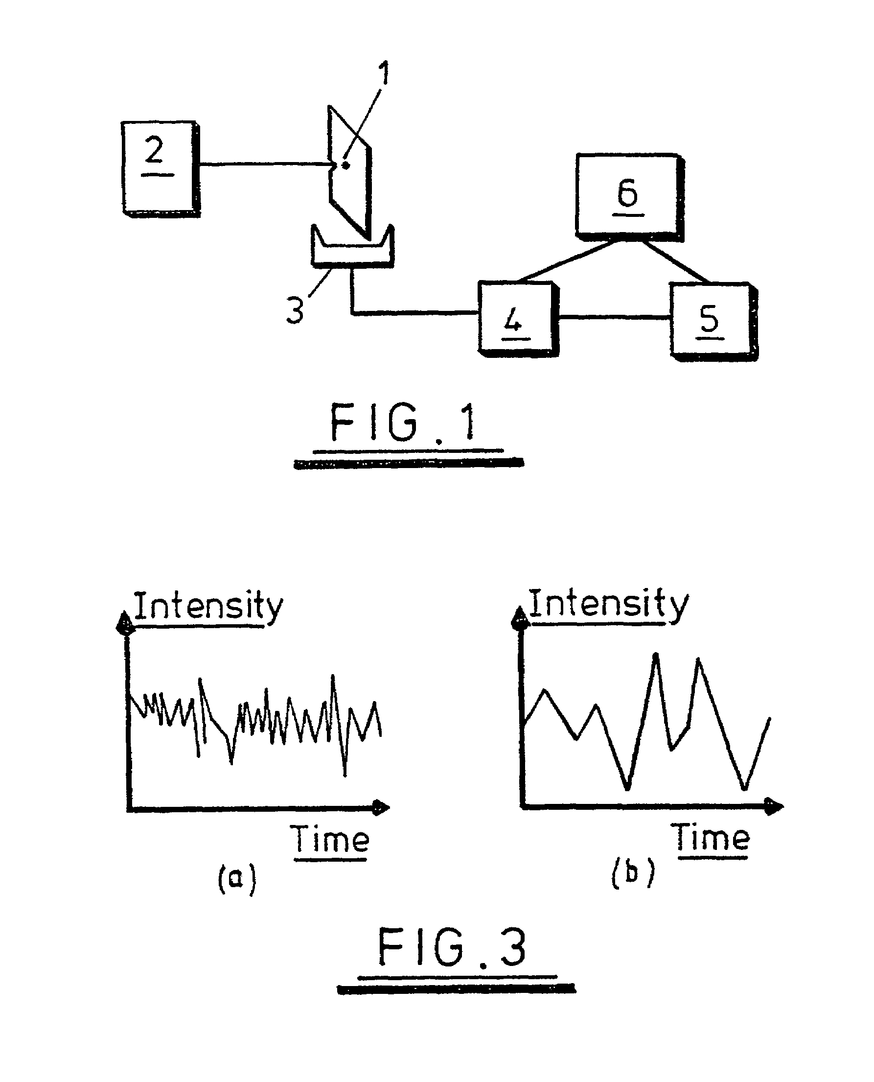
[0075]Referring first to FIG. 1, a fluorescence detection apparatus comprises a sample 1 and a laser 2 which is arranged to illuminate the sample 1 with a continuous beam of light. A detector 3 is provided to detect photons emitted by the sample 1. The detector 3 may be provided with a filter (not shown) to prevent the detection of light emitted by the laser 2. An auto-correlator 4 correlates the detected signal to give a correlation, and a processor 5 processes the output of the detector to measure the characteristic lifetime of the fluorophores comprising the sample 1. The operation of the processor 5 is described below. The output from the processor 5 and / or the auto-correlator 4 may be displayed on a monitor 6.

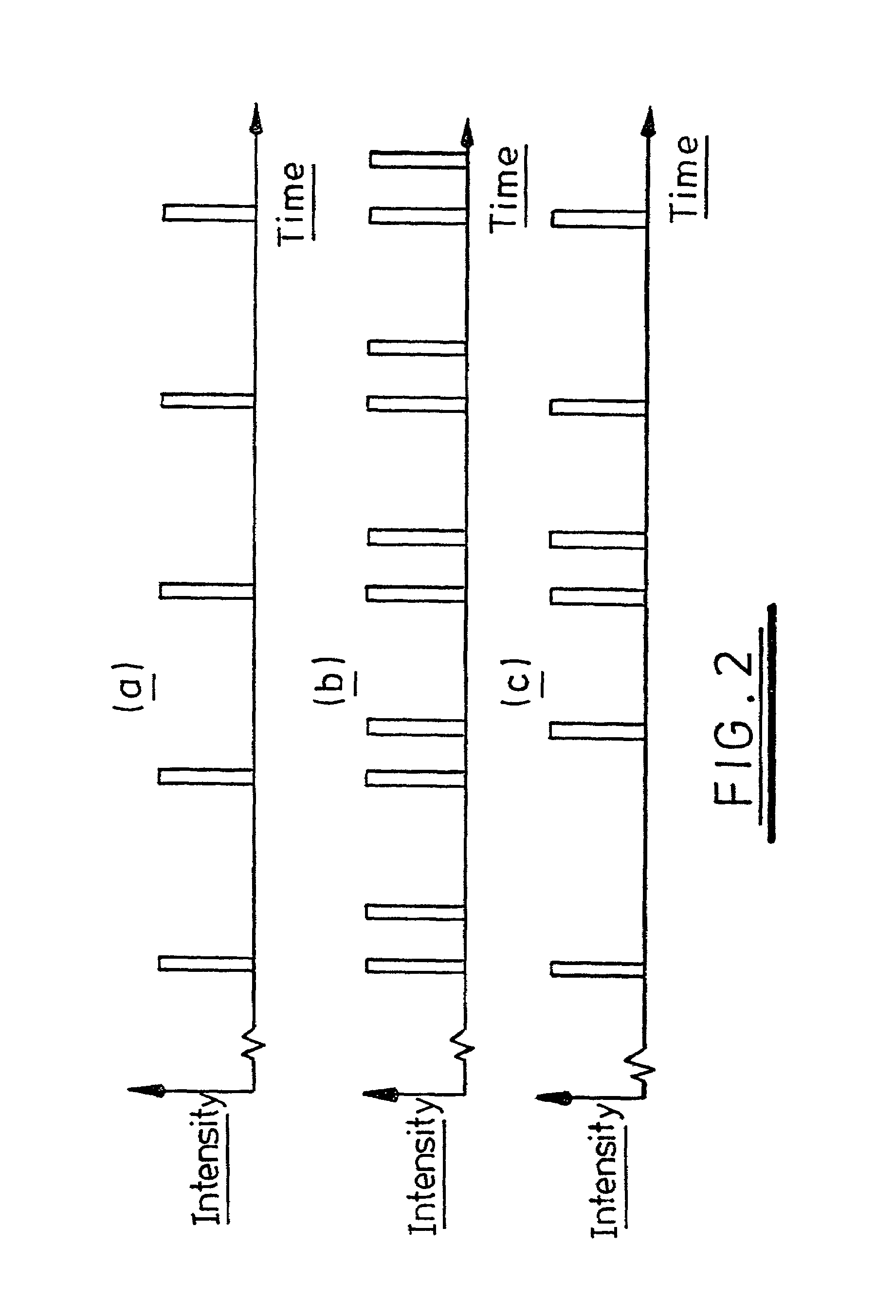
[0076]FIG. 2 illustrates the principle of operation of the invention. FIG. 2a represents the result of illuminating a single fluorophore with a continuous beam of high intensity light. A photon in the high intensity beam will excite the fluorophore to an excited state, and...


PUM


Abstract

An analysis for determining a characteristic cycle time of a sample. Active elements in the sample are excited with sufficient intensity and duration larger than the characteristic cycle time that at least some of the active elements are re-excited to an excited state substantially immediately following relaxation to a ground state, detecting quanta emitted by the active elements in the sample to obtain a detected signal, and analyzing the detected signal to derive the characteristic cycle time. The number of active elements in the sample and the intensity of the excitation are such that quanta are detected in a stream in which individual quanta are distinguishable from each other.

Description

RELATED APPLICATIONS[0001]This is a US national phase filing under 35 U.S.C. § 371 of PCT / GB 99 / 02047 filed Jul. 8, 1999 and claims priority from GB 90814715.0 filed Jul. 8, 1998, GB 9827903.7 filed Dec. 19, 1998 and GB 9827910.2 filed Dec. 19, 1998.BACKGROUND[0002]1. Technical Field[0003]This invention relates to a method and apparatus for the analysis of a sample, and particularly though not exclusively to fluorescence analysis.[0004]2. Related Art[0005]Fluorescence analysis is an important experimental tool for both chemists and biologists, and is of particular interest to pharmaceutical researchers.[0006]A known method of analysing fluorescence comprises exciting a sample of many hundreds of fluorophores with an intense pulse of light from a laser. The intensity of fluorescence emitted by the sample at a given delay following excitation is detected. The sample is excited again, and the intensity of fluorescence emitted by the sample at a different delay following excitation is d...

Claims


Application Information

Patent Timeline
IPC IPC(8): G01N21/76F21V9/16G01J3/443G01N21/64G01N31/22G01N33/533G01N33/542G01N33/58
CPCG01N31/229
Inventor LLOYD, CHRISTOPHER J.CLARKE, DAVID J.
Owner VICTORIA UNIVERSITY OF MANCHESTER
Why Eureka
Try Eureka