Process and system for separating solids from combined sewer overflows

a combined sewer and solids technology, applied in the direction of sedimentation settling tanks, separation processes, liquid displacement, etc., can solve the problems of reducing the capacity of conventional storage and ducting systems, and affecting the quality of water

Inactive Publication Date: 2006-07-20
HUBBELL ROTH & CLARK
View PDF32 Cites 17 Cited by
  • Summary
  • Abstract
  • Description
  • Claims
  • Application Information

AI Technical Summary

Benefits of technology

[0015] The retention treatment basin has one or more influent channels that duct the influent into the basin. Upon entry, if the volume of influent is sufficient, its surface rises to above the level of a weir that extends upwardly from the floor. The influent then flows across the weir and into a cell. At least some of the settlable solids are retained in the cell. A baffle is supported above the floor. Its primary purpose is to trap at least some of the floatable solids that are passed into the cell across the weir. Part of the influent passes under the baffle through a space defined between a lower region of the baffle and the floor.
[0016] One or more up-flow screen systems extend generally horizontally from the baffle. These screen systems are pervious to fluids. They receive the influent and arrest movement of floatable solids therethrough, thereby creating a floatable-solids depleted effluent upstream of the one or more screen systems. Preferably the one or more screen systems include a bar grating arrangement that is formed from bars that have a triangular cross-section.

Problems solved by technology

However, melting snow or heavy, sustained rain may result in the capacity of conventional storage and ducting systems to be exceeded.
But, it would clearly be undesirable if sewers were to backup into streets and basements.
Combined sewer systems are frequently found in older urban communities, in which discharges from CSOs may significantly degrade water quality.
It does not allow pipes with an inherent-capacity constraint to deliver all effluent to the treatment plant.
Further, treatment plants may not be large enough to deal with an incoming volume over a lengthy period.
In such situations, effluent may overflow certain points in the system.
However, such practices may violate construction restrictions that may be environmentally imposed.
Primary concerns relating to retention treatment basins in conventional CSOs are their costs and environmental impact.

Method used


Image

  • Process and system for separating solids from combined sewer overflows
  • Process and system for separating solids from combined sewer overflows
  • Process and system for separating solids from combined sewer overflows

Examples


Embodiment Construction

)

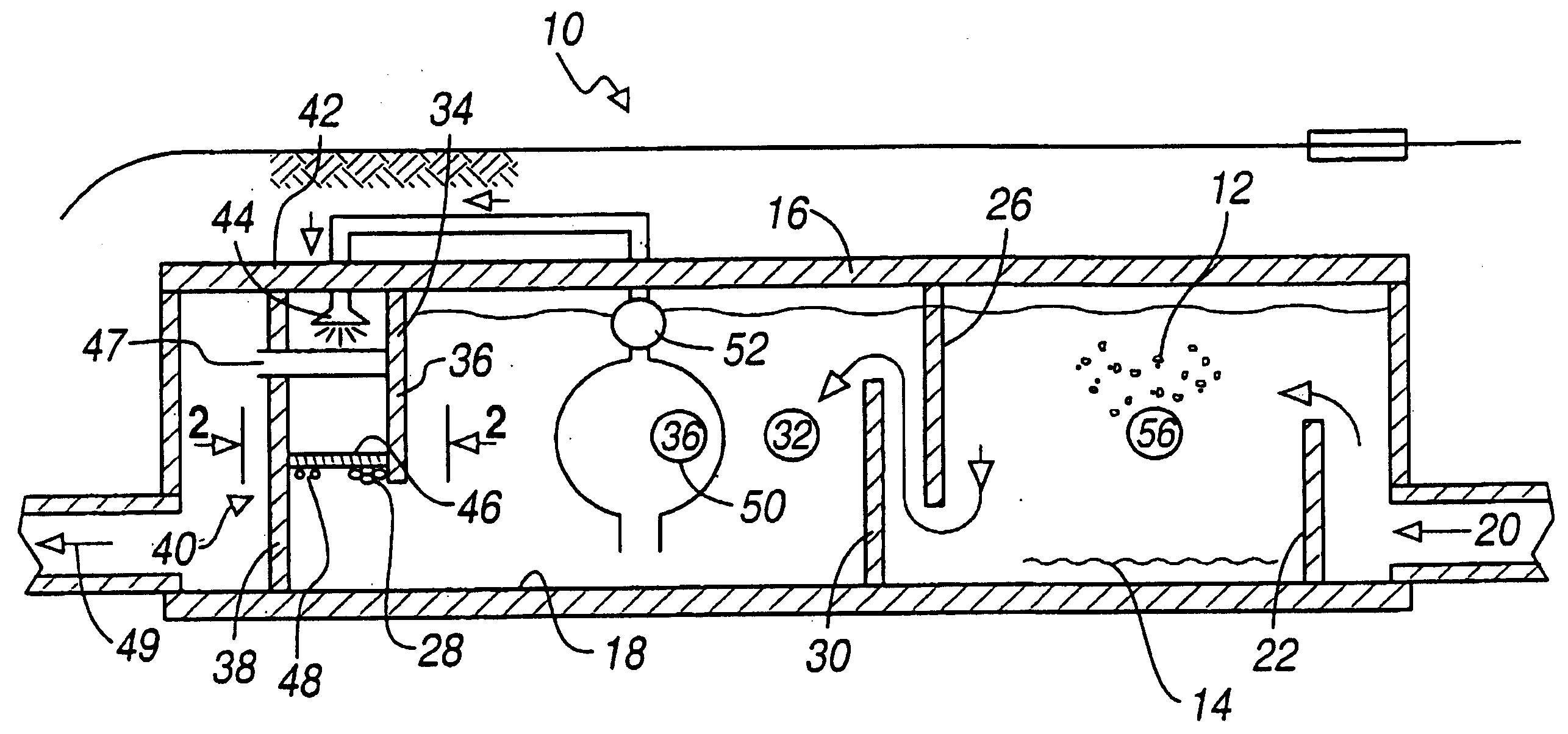
[0023] Turning first to FIG. 1, there is depicted a retention treatment basin 10 that handles an influent of combined wastewater and sewer overflows. The influent includes floatable 12 and settlable solids 14. The basin is provided with a a floor 18 and may have a ceiling 16. One or more influent channels 20 duct the influent into the basin. Upon entry, the influent confronts a weir assembly 22 that extends upwardly from the floor. The weir assembly 22 is for simplicity depicted as having a single wall. It should be realized, however, the weir assembly 22 may have a plurality of wall systems that may or may not be interconnected. Depending upon flow rate, volume, time and weir height, the level of the influent may rise above the weir assembly 22 before passage into a cell 24. At least some of the settlable solids 14 are retained in the cell 24.

[0024] The embodiment of retention basin 10 that is depicted in FIG. 1 has two cells that respectively are indicated by the reference numer...


PUM

PropertyMeasurementUnit
lengthaaaaaaaaaa
lengthaaaaaaaaaa
gravityaaaaaaaaaa

Abstract

A retention treatment basin system and method 10 that handles an influent of combined wastewater and sewer overflows. The influent includes floatable 12 and settlable solids 14. The basin includes a ceiling 16. The retention treatment basin has one or more influent channels 20 that duct the influent into the basin. A weir assembly 22 extends upwardly from the floor, over which the influent flows. A cell 24 receives the influent passing over the weir. At least some of the settlable solids are retained in the cell. A baffle 26 traps at least some of the floatable solids in the cell. Part of the influent passes under the baffle. One or more up-flow screen systems 28 with bars having a triangular cross-section extend from the baffle that are pervious to fluids for receiving the influent and arresting movement of floatable solids therethrough. The screen system creates a floatable-solids depleted effluent.

Description

BACKGROUND OF THE INVENTION [0001] 1. Field of the Invention [0002] The invention relates to the processes practiced by and construction of wastewater treatment plants. More specifically, the invention relates to a system for removing solids from combined sewer overflows. [0003] 2. Background Art [0004] Combined sewer overflows (CSOs) are discharges of wastewater from a collection system that carries sanitary and storm water. Combined sewer systems deliver the wastewater to a wastewater treatment plant (WWTP). However, melting snow or heavy, sustained rain may result in the capacity of conventional storage and ducting systems to be exceeded. Accordingly, access wastewater sometimes charge directly into surface water. In the past, this practice has been accepted in situations where it was believed that receiving waters could handle the overflow without serious damage. But, it would clearly be undesirable if sewers were to backup into streets and basements. [0005] Combined sewer syste...

Claims


Application Information

Patent Timeline
Patent Type & Authority Applications(United States)
IPC IPC(8): B01D36/04
CPCB01D21/0012B01D21/003B01D21/0042B01D21/2433B01D21/2444C02F1/001C02F2001/007C02F2103/001E03F5/14B01D21/0039
Inventor BRODY, DAVID
Owner HUBBELL ROTH & CLARK
Why Eureka
Try Eureka