Camera system
a camera system and camera technology, applied in the field of cameras, can solve problems such as the proper imaging uni
- Summary
- Abstract
- Description
- Claims
- Application Information
AI Technical Summary
Benefits of technology
Problems solved by technology
Method used
Image
Examples
first embodiment
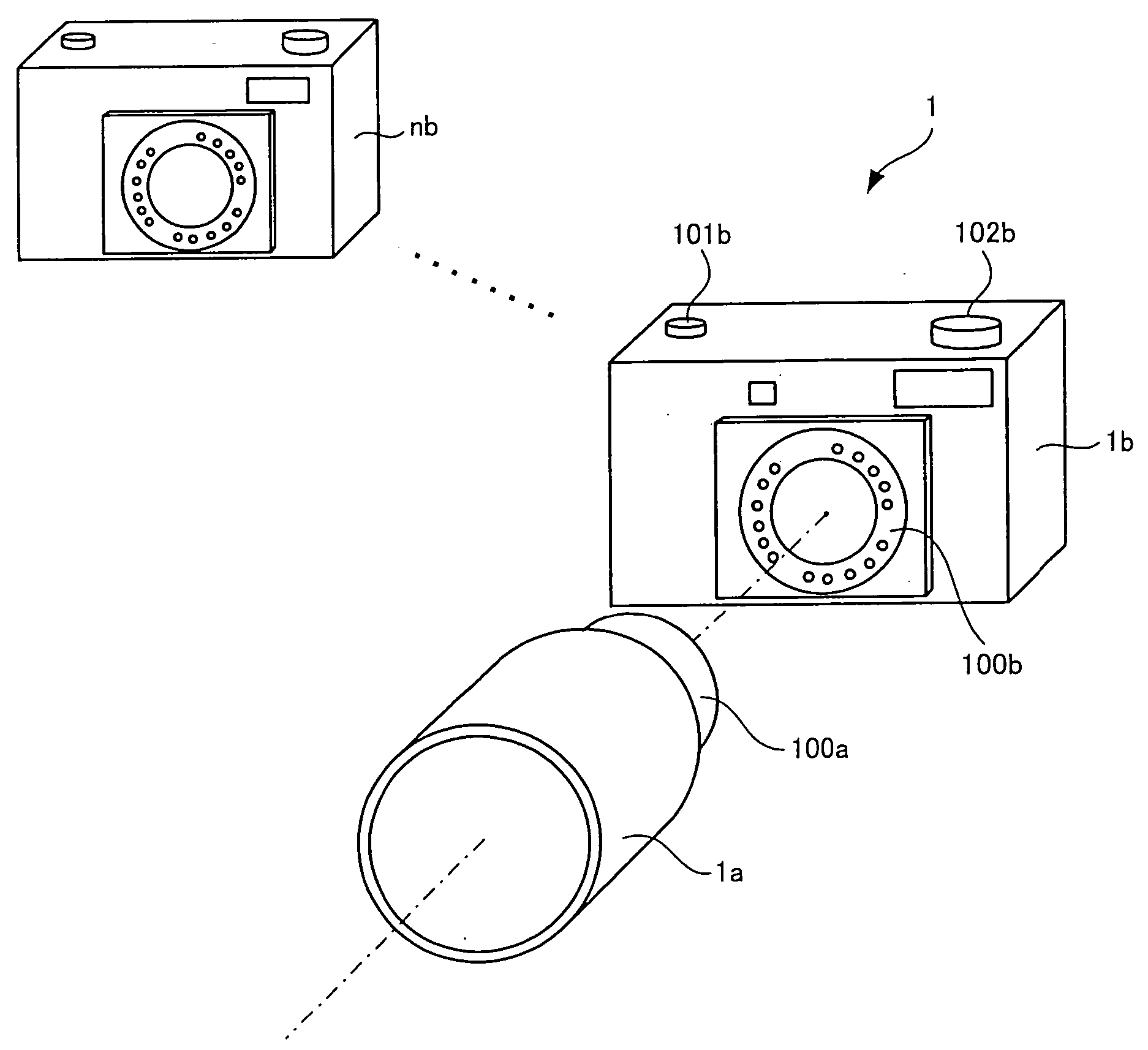
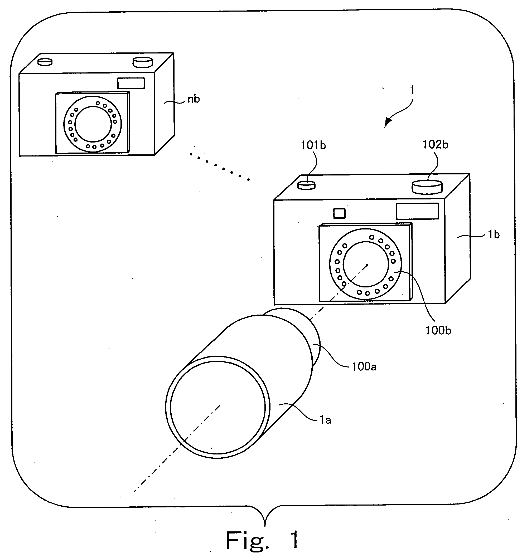
[0038]FIG. 1 shows a camera system 1 according to the present invention.
[0039] The camera system 1 includes an imaging unit 1a and main units 1b through nb and is configured such that the imaging unit 1a can be detachably attached to any of these main units.
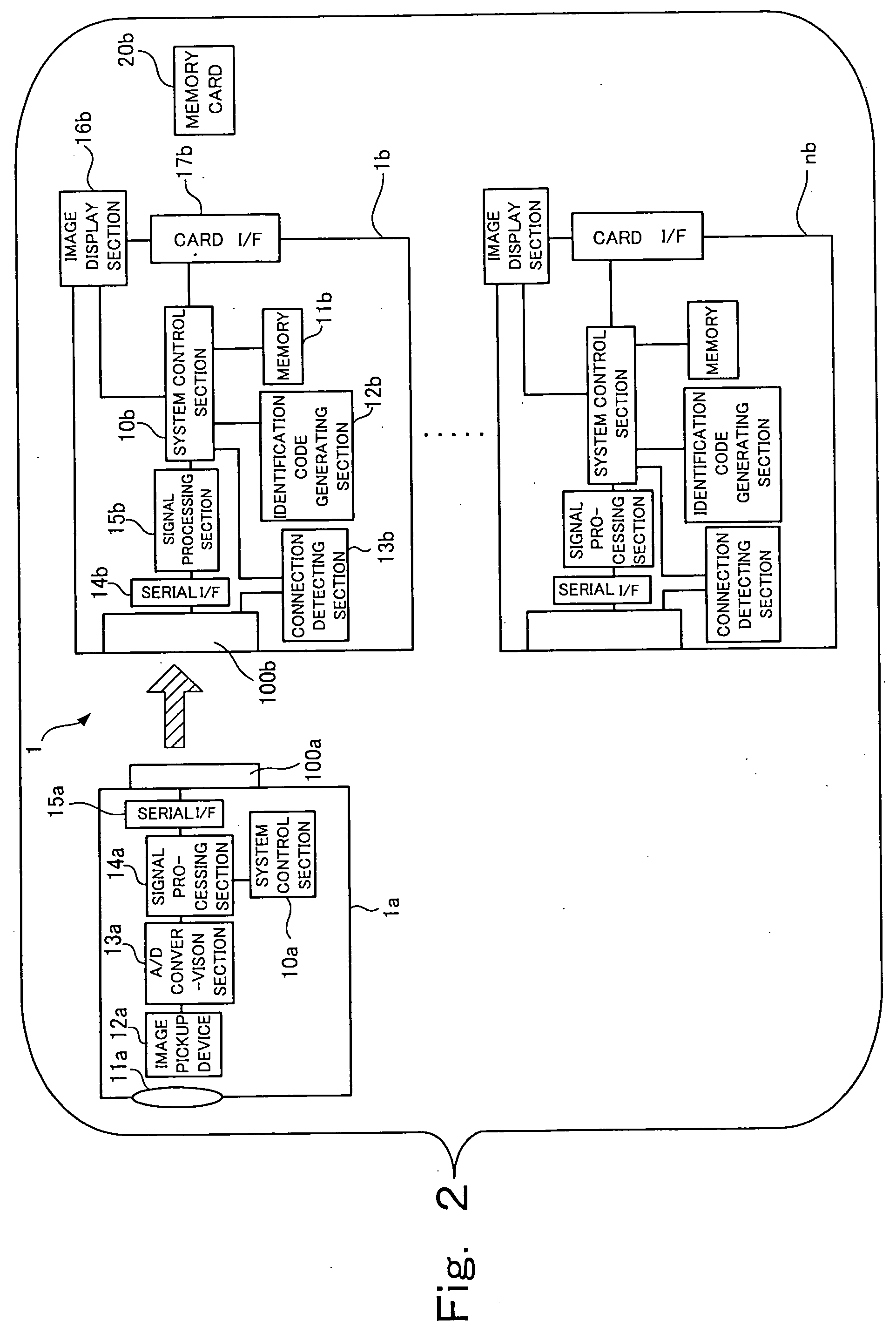
[0040] The imaging unit 1a shown in FIG. 1 is a proper one and the main units 1b through nb are plural types of main units to which the proper imaging unit 1a can be attached. The camera system 1 will be described assuming that the main units 1b through nb include an improper one (e.g. a main unit incompatible with the specification of the imaging unit, a completely counterfeit unit, etc.). The main unit 1b representing the main units 1b through nb shown in FIG. 1 has a release button 101b and a shooting mode dial 102b. The imaging unit 1a and the main unit 1b have mount sections 100a and 100b provided with multiple mount contacts, respectively. When the imaging unit 1a is attached to the main unit 1b, the mount contacts of both...
second embodiment
[0074]FIG. 4 shows a camera system 2 according to the present invention, which has been improved to perform mutual identification.
[0075]FIG. 4 shows imaging units 1aa through naa which include an improper one and main units 1b through nb that also include an improper one. Although only the imaging unit has the identification section in FIG. 1, both the imaging unit and the main unit have the respective identification sections in FIG. 4. In the description of the second embodiment, the same elements as those of the first embodiment are denoted by the same names and reference characters as those of the first embodiment.
[0076]FIG. 5 shows the internal structures of the imaging unit 1aa and the main unit 1b each illustrated as a representative example of those shown in FIG. 4.
[0077] As shown in FIG. 5, the second system control section 10b of the main unit 1b is provided with an identification function and the imaging unit 1aa is provided with an identification code generating section...
PUM
 Abstract
Description
Claims
Application Information
 - R&D
- Intellectual Property
- Life Sciences
- Materials
- Tech Scout
- Unparalleled Data Quality
- Higher Quality Content
- 60% Fewer Hallucinations
Browse by: Latest US Patents, China's latest patents, Technical Efficacy Thesaurus, Application Domain, Technology Topic, Popular Technical Reports.
© 2025 PatSnap. All rights reserved.Legal|Privacy policy|Modern Slavery Act Transparency Statement|Sitemap|About US| Contact US: help@patsnap.com


