Locking cross bar

Inactive Publication Date: 2006-07-27
KONSTANT PRODS
View PDF12 Cites 17 Cited by
  • Summary
  • Abstract
  • Description
  • Claims
  • Application Information

AI Technical Summary

Benefits of technology

[0007] In addition, the present invention provides an improved locking cross bar for creating, or that can be used to create, a support surface between front and rear deck beams of a rack-type storage system. For example, the present invention provides a rack storage system having at least one locking cross bar having a support surface, a front end and a back end. Means are provided on the front end of the locking cross bar for securing the locking cross bar to the front deck beam to prevent undesired movement of the cross bar, as well as means on the front deck beam to cooperate with said securing means. Securing means may also include a locking tab, hook, lip or other structure to engage the front deck beam cooperating means. Means on the back end of the locking cross bar to prevent undesired movement, lock and / or be supported by the rear deck beam may also be provided.
[0015] Still a further object of the present invention is to provide an improved locking cross bar system to create shelves for rack storage structures that saves costs, provides adequate strength, enables system flexibility, and is dependable. Inventor's Definition of the Terms

Problems solved by technology

However, in this configuration, the slats are prone to being knocked-out, skewed or otherwise misaligned between the deck beams as a result of, among other things, contact with a pallet or fork lift or being otherwise inadvertently disturbed by the warehouse personnel.
If this shifting or knock-out of one or more slats is unknown to the warehouse personnel, subsequent placement of a load could result in the load falling, leading to injury to the personnel and / or damages to the load, equipment or rack structure.
At best, making sure that the slats are properly positioned between the deck beams is time consuming for the warehouse personnel.
Although an improvement, this method has disadvantages such as increased construction costs and decreased flexibility.

Method used


Image

  • Locking cross bar
  • Locking cross bar
  • Locking cross bar

Examples


Embodiment Construction

[0031] Set forth below is a description of what is currently believed to be the preferred embodiments or best representative examples of the inventions claimed. Future and present alternatives and modifications to the embodiments and preferred embodiments are contemplated. Any alternatives or modifications which make insubstantial changes in function, purpose, structure or result are intended to be covered by the claims of this patent.

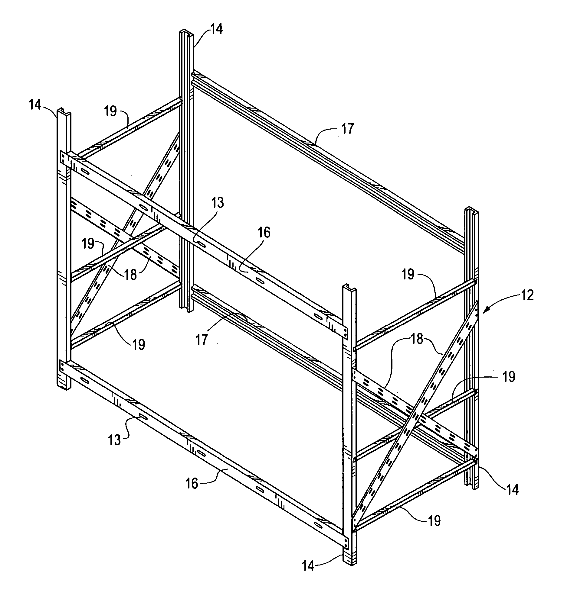
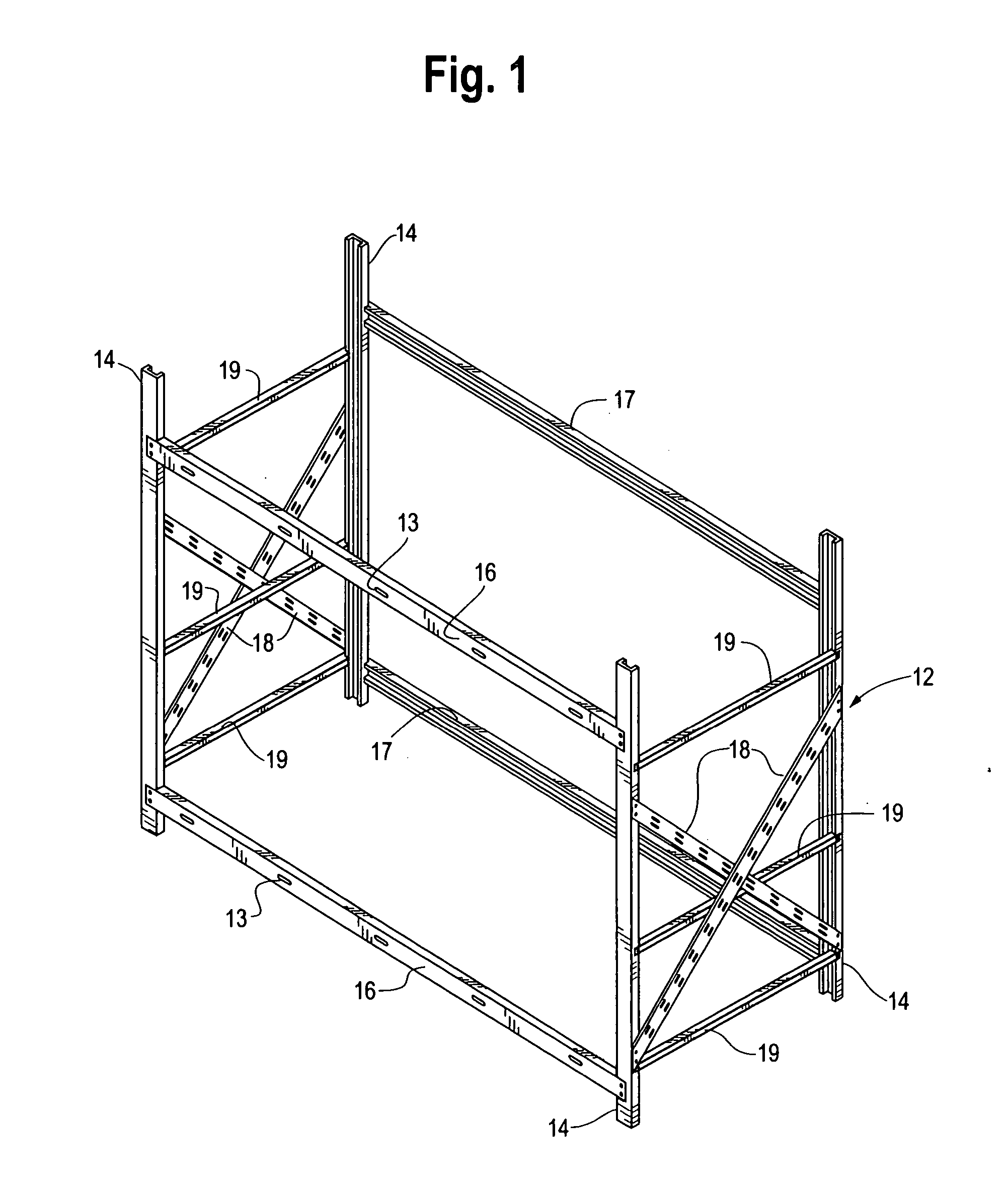
[0032] The structural components and configuration of a typical storage rack truss 12 is shown generally in FIG. 1. Such components include a plurality of spaced parallel columns 14, a plurality of generally horizontal front deck beams 16 (FIG. 1 also showing a modification, i.e. apertures, holes or slots 13, to the front deck beams 16 consistent with a preferred embodiment of the present invention) interconnecting front columns 14, and a plurality of generally horizontal rear deck beams 17 that interconnect the rear columns 14. Support braces 18 and ...


PUM


Abstract

A cross bar forming a support surface between parallel deck beams of rack-type storage systems to create storage shelves, the cross bars being lockable and readily removable and reusable.

Description

BACKGROUND OF THE INVENTION [0001] The present inventions relate generally to shelf-type storage racks systems and, more particularly, to improved cross bars used to create storage shelves. The cross bars of the present inventions are locked or secured against undesired movement without bolts and the like to create a shelf so that loads are properly supported. The locking cross bars are also readily removeable and reusable. [0002] Shelf-type storage racks are widely known in the storage and warehouse industry. Typical shelf-type storage racks include at least four vertical columns rigidly interconnected by generally horizontal deck beams which are positioned in a transverse relation with pairs of columns that are spaced by horizontal and diagonal members commonly referred to as storage rack trusses. The storage rack trusses may be arranged as a series of back-to-back arrays with each array, including the horizontal deck beam, facing an access aisle. As is typical in known, shelf-typ...

Claims


Application Information

Patent Timeline
IPC IPC(8): A47B47/00A47B47/02A47F5/01
CPCA47B47/021A47B47/028A47F5/01
Inventor KONSTANT, ANTHONY N.
Owner KONSTANT PRODS
Why Eureka
Try Eureka