Counter rotating generator

a generator and rotating technology, applied in the direction of machines/engines, mechanical energy handling, mechanical apparatus, etc., can solve the problems of inability to easily dissipate heat buildup by friction engagement with brushes, and the relative rotational velocity of such generators must be limited

Inactive Publication Date: 2006-07-27
FLORES PAUL JR
View PDF16 Cites 51 Cited by
  • Summary
  • Abstract
  • Description
  • Claims
  • Application Information

AI Technical Summary

Problems solved by technology

One of the drawbacks of such counter rotating generators is the tendency for them to overheat due to friction between brushes and slip rings or commutators.
Such commutators and slip rings have relatively small diameters and thus the frictional engagement with the brushes is incapable of easily dissipating the heat buildup therein.
As a result, the relative rotational velocity of such generators must be limited.

Method used


Image

  • Counter rotating generator
  • Counter rotating generator
  • Counter rotating generator

Examples


Embodiment Construction

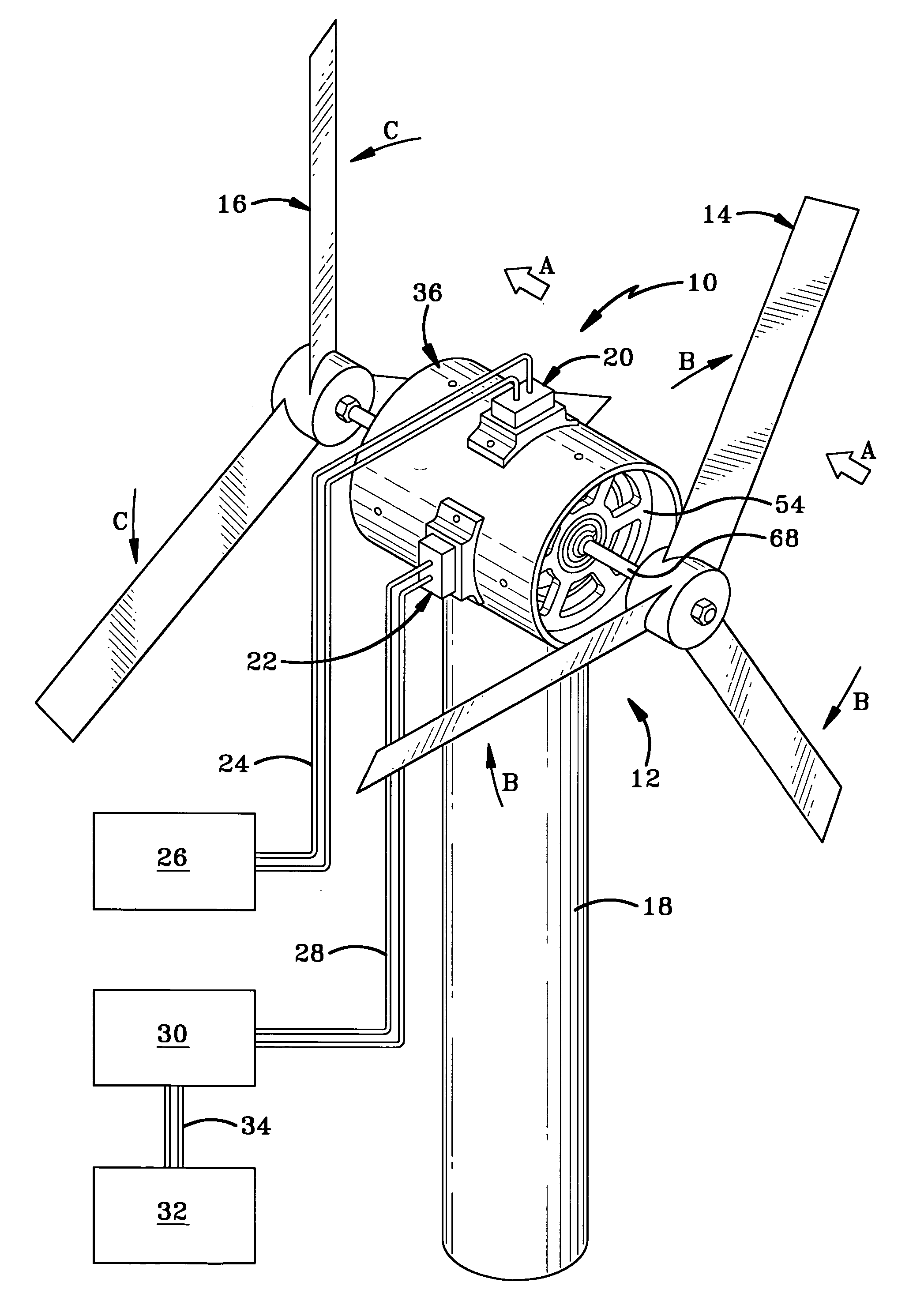
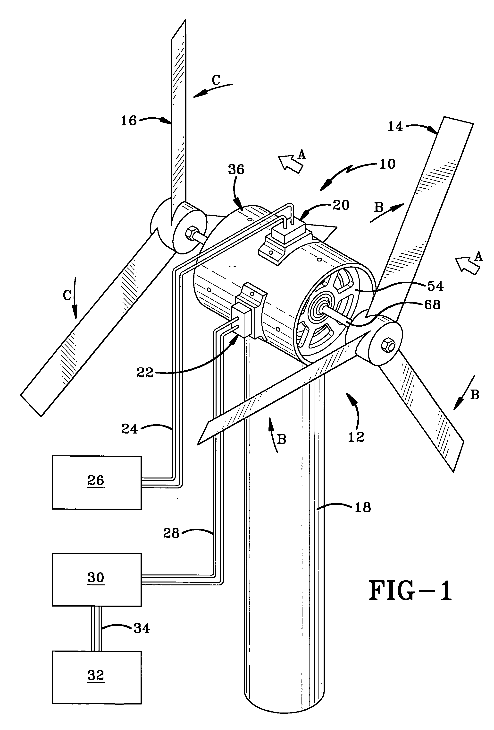
[0017] The counter rotating generator of the present invention is indicated generally at 10 in FIGS. 1-2. FIG. 1 shows generator 10 being used as part of a wind generator 12 wherein air moving in the direction indicated by arrows A rotates a first propeller 14 in the direction indicated by arrows B and a second propeller 16 in the direction indicated by arrows C which is opposite to the direction indicated by arrows B. Generator 10 is seated atop a stand 18 and has first and second brush assemblies 20 and 22 mounted thereon. A pair of wires 24 is in communication with first brush assembly 20 and an electrically operated device 26. Another pair of wires 28 is in electrical communication with brush assembly 22 and a regulator 30 which is in electrical communication with electrically operated device 32 via a pair of wires 34.

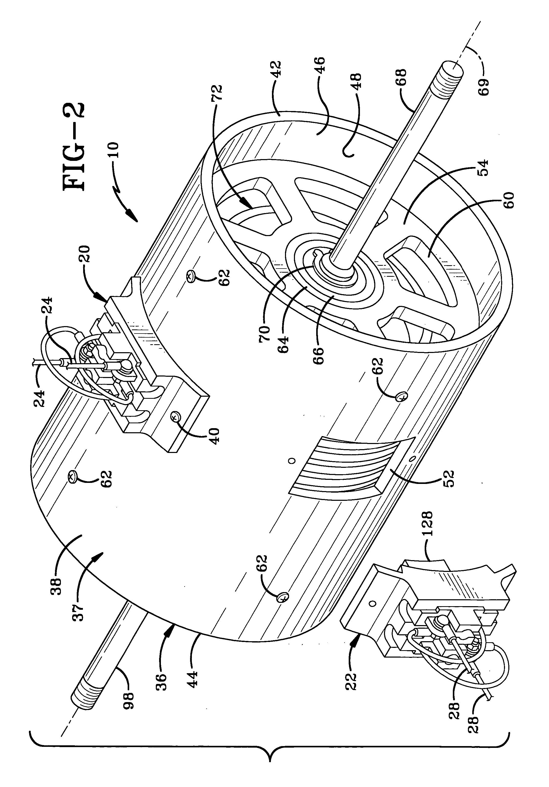
[0018] With reference to FIGS. 2 and 3, generator 10 includes a rigid mounting frame in the form of an external housing 36 which includes a cylindrical sidewall 3...


PUM


Abstract

A counter rotating generator has an outer housing including a cylindrical sidewall defining a pair of openings and a pair of circular mounting plates connected to the outer housing adjacent respective opposed ends thereof. A first shaft and an armature mounted thereon are rotatably mounted on one mounting plate. A second shaft and a field magnet mounted thereon via an inner housing is rotatably mounted on the other mounting plate in a direction opposite the armature. Slip rings are mounted on and encircle the inner housing. A pair of brush assemblies are mounted on the outer housing and extend respectively through the openings in sidewall thereof with brushes contacting the slip rings between and adjacent the inner housing and the outer housing sidewall. The large-diameter slip rings more quickly dissipate heat caused by frictional engagement of the brushes and slip rings, thus allowing the generator to operate at higher rates of revolution and higher temperatures.

Description

BACKGROUND OF THE INVENTION [0001] 1. Technical Field [0002] The invention relates generally to counter rotating generators for producing electrical power. More particularly, the invention relates to such a generator which may be used at relatively high RPM's and relatively elevated temperatures. Specifically, the invention relates to such a generator having slip rings encircling a housing in which the field and armature are housed. [0003] 2. Background Information [0004] Counter rotating generators are well-known in the art and their basic form involves a magnetic field or field part which is rotatable in a first direction and an armature or winding part which is rotatable in the opposite direction. This concept is particularly useful in wind generators and may also be used via the relative movement between the generator, propellers and other fluids or via any other power source for respectively rotating the field and the armature. With regard to wind generators, the counter rotati...

Claims


Application Information

Patent Timeline
Patent Type & Authority Applications(United States)
IPC IPC(8): H02K23/60
CPCF03D1/025F03D9/002H02K7/183H02K16/005Y02E10/725F03D9/25Y02E10/72
Inventor FLORES, PAUL JR.
Owner FLORES PAUL JR
Why Eureka
Try Eureka