Ink jet print head, ink jet printing apparatus, and method for manufacturing ink jet print head

a technology of ink jet printing and print head, which is applied in the direction of printing, etc., can solve the problems of delaying ink supply, affecting assembly operations, and increasing the size of the whole print head, so as to reduce the resistance of ink flow, increase the speed of ink ejection, and supply smoothly

Active Publication Date: 2006-07-27
COPYER
View PDF13 Cites 7 Cited by
  • Summary
  • Abstract
  • Description
  • Claims
  • Application Information

AI Technical Summary

Benefits of technology

[0018] It is an object of the present invention to provide an ink jet print head that smoothly supplies ink to make it possible to increase ink ejection speed to achieve high-speed printing, as well as an ink jet printing apparatus using the ink jet print head and a method for manufacturing the ink jet print head.
[0019] It is another object of the present invention to provide an ink jet print head that can be assembled easily and efficiently, as well as an ink jet printing apparatus using the ink jet print head and a method for manufacturing the ink jet print head.
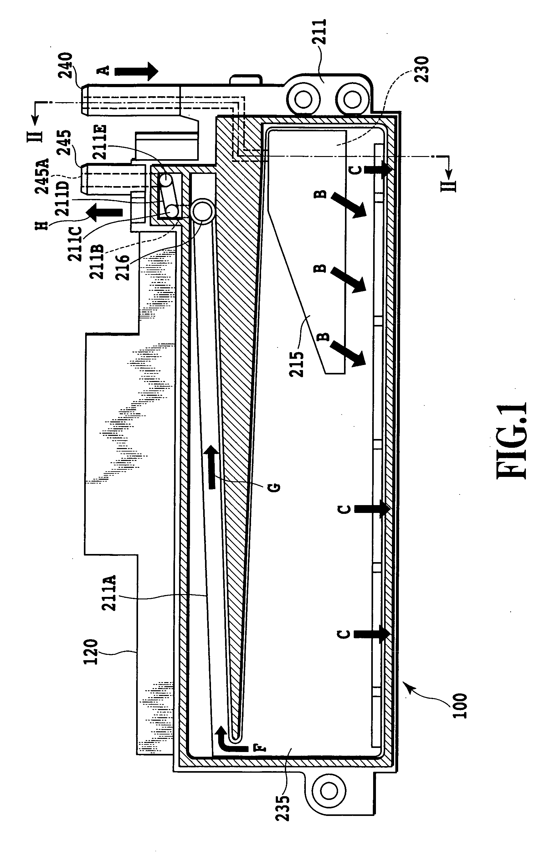
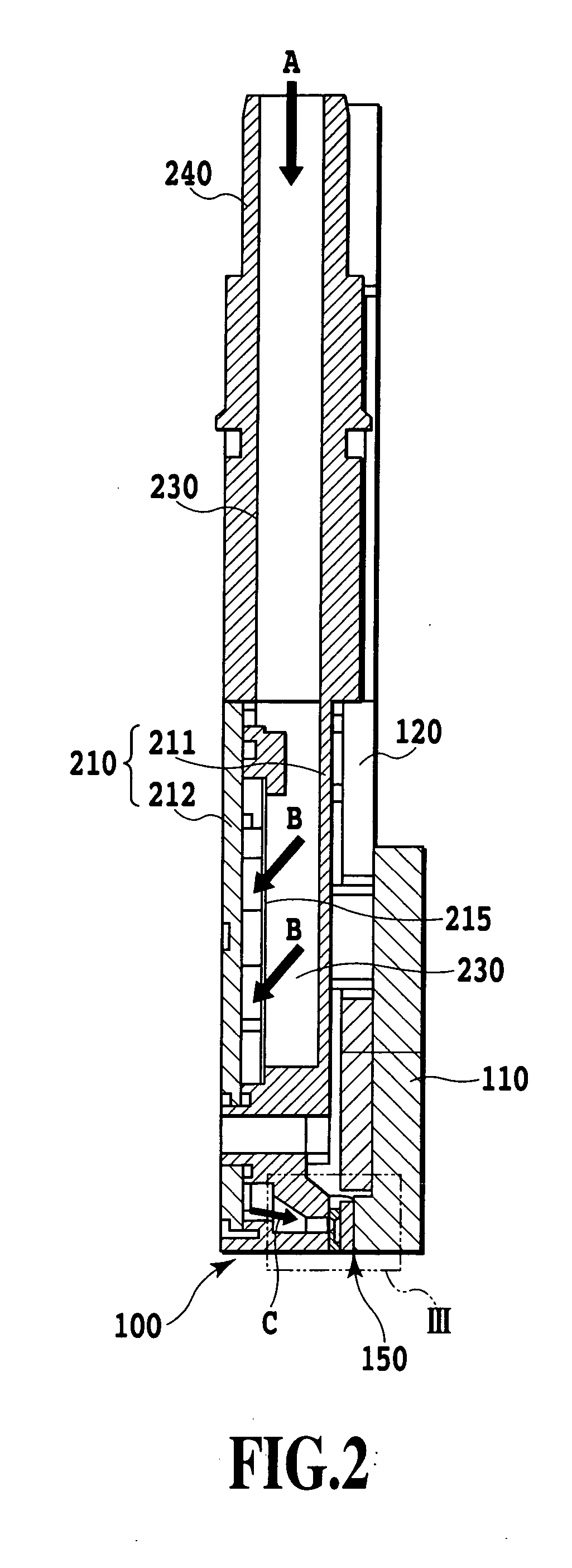
[0029] According to the present invention, the filter partitions the ink storing chamber into the first and second ink storing chambers. Ink stored in the first ink storing chamber is supplied to the common liquid chamber. Ink introduced from the ink introducing section into the second ink storing chamber is supplied to the first ink storing chamber through the filter. This makes it possible to provide a large-area filter to reduce ink flow resistance. The ink can thus be smoothly supplied. It is therefore possible to increase the speed at which the ink is ejected from ejection openings in the ink jet print head, thus achieving high-speed printing.
[0030] Further, the first and second storing chamber members are joined together to form the first and second ink storing chambers partitioned by the filter. This improves the operability of assembly of the ink jet print head.

Problems solved by technology

However, the conventional print head described above may present the following problems.
This increases the size of the whole print head.
Thus, with a high driving frequency with which ink is ejected, the ink supply may be delayed to preclude the ink from being ejected.
This degrades the efficiency of assembly operations.

Method used


Image

  • Ink jet print head, ink jet printing apparatus, and method for manufacturing ink jet print head
  • Ink jet print head, ink jet printing apparatus, and method for manufacturing ink jet print head
  • Ink jet print head, ink jet printing apparatus, and method for manufacturing ink jet print head

Examples


Embodiment Construction

[0050] An embodiment of the present invention will be described with reference to the drawings.

[0051]FIG. 10 is a schematic diagram showing the configuration of an ink jet printing apparatus 1000 that can print full-color images, as an example of a printing apparatus to which an ink jet print head in accordance with the present invention is applicable.

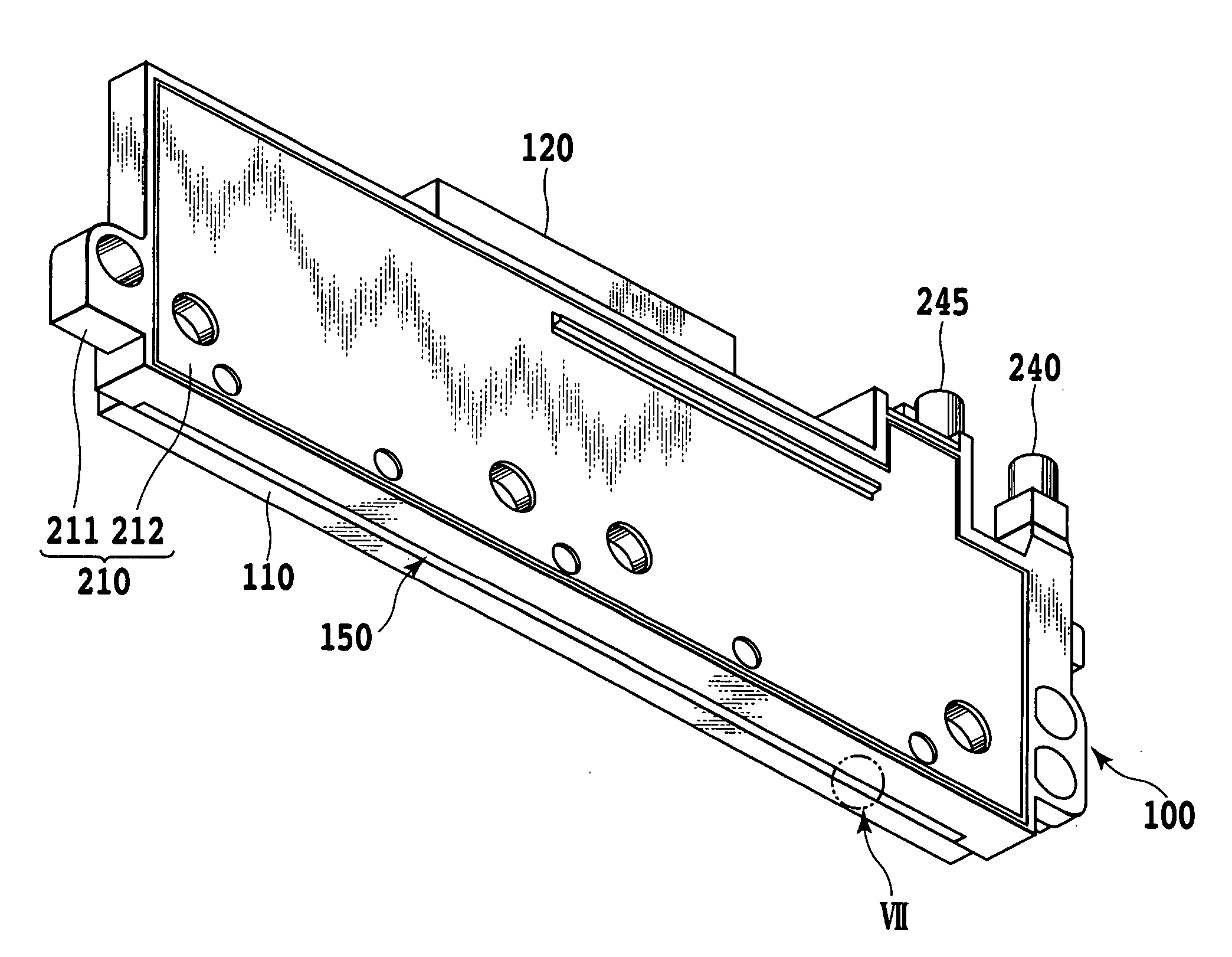
[0052] The printing apparatus 1000 in the present example comprises an ink jet print head 100, a sheet feeding device 50, a sheet discharging device 60, an image forming section 45, a conveying device 70, an ink tank 1, and an ink supply device 90. A sheet 51 as a print medium is supplied to the conveying device 70 by the sheet feeding device 50. The conveying device 70 then conveys the sheet 51, which thus passes by the position of the image forming section 45. The image forming section 45 prints an image containing characters, pictures, or the like on the sheet 51 by ejecting ink from the print head 100 on the basis of an instructi...


PUM


Abstract

According to the present invention, ink is smoothly supplied so as to increase ink ejection speed to achieve high-speed printing. Thus, a filter (215) is used to partition an ink storing chamber into a first and second storing chambers (235, 230). Ink stored in the first storing chamber (235) is supplied to a common liquid chamber in an ejection element (150). Ink introduced into the second ink storing chamber (230) through a joint (240) is supplied to the first storing chamber (235) through the filter (215). An ink storing chamber member (211) is joined to an ink storing chamber cover member (212) to form the first and second ink storing chambers (235, 230) partitioned by the filter (215).

Description

[0001] This application claims priority from Japanese Patent Application No. 2005-014561 filed Jan. 21, 2005, which is hereby incorporated by reference herein. BACKGROUND OF THE INVENTION [0002] 1. Field of the Invention [0003] The present invention relates to an ink jet print head that can eject ink from ejection openings, an ink jet printing apparatus using the ink jet print head, and a method for manufacturing the ink jet print head. [0004] 2. Description of the Related Art [0005] In an ink jet printing system, an ink jet print head that can eject ink is used to attach ink droplets ejected by the print head to a print medium such as paper. The ink jet printing system makes only very low noise and enables high-speed printing. The ink jet printing system also enables ordinary paper to be printed. Among such ink jet print heads, those using heating elements as energy generators for ejecting ink have recently been gathering much attention because of the ease with which these print he...

Claims


Application Information

Patent Timeline
Patent Type & Authority Applications(United States)
IPC IPC(8): B41J2/175
CPCB41J2/17513
Inventor FUJII, TOMOHIROISHINAGA, HIROYUKIMUKAI, KAYO
Owner COPYER
Why Eureka
Try Eureka