Wireless communication system, receiver, demodulation method used for the system and receiver, and program thereof

a communication system and receiver technology, applied in the field of wireless communication systems, can solve problems such as difficulty in the receiver b>12, estimation nb, and problems in the related art as described abov

Inactive Publication Date: 2006-07-27
NEC CORP
View PDF5 Cites 22 Cited by
  • Summary
  • Abstract
  • Description
  • Claims
  • Application Information

AI Technical Summary

Benefits of technology

[0028] An object of the present invention is to construct a receiver in a wireless communication system having a receiver by which a signal transmitted through plural transmission antennae is received through plural reception antennae, the receiver being capable of steadily calculating bit likelihood without requiring a selection processing.
[0030] To solve the above problems, a wireless communication system according to the first aspect of the present invention has a receiver comprising two or more reception antennae, two or more adaptive nulling devices, and an adaptive demodulation device, and receives signals transmitted from a transmitter having two or more transmission antennae. Since this structure is adopted, a receiver can be constructed with capability to calculate bit likelihood steadily, without requiring a selection processing.
[0031] In a wireless communication system according to the second aspect of the present invention, the adaptive demodulation device comprised in the wireless communication system of the first aspect has a selection / combining device, and performs one or both of selection and combining. Since this structure is adopted, a receiver can be constructed with capability to calculate bit likelihood steadily, without requiring a selection processing.
[0032] In a wireless communication system according to the third aspect of the present invention, the adaptive nulling devices comprised in the wireless communication system of the first aspect have a rearrangement control device, and determine a rearrangement in nulling devices, based on the channel quality of signals. Since this structure is adopted, a receiver can be constructed with capability to calculate bit likelihood steadily, without requiring a selection processing, and to perform efficient control in compliance with states of channels.
[0033] In a wireless communication system according to the fourth aspect of the present invention, the adaptive demodulation device comprised in the wireless communication system of the first aspect has a switching control device, and controls demodulation devices to be operated, based on the channel quality of signals. Since this structure is adopted, a receiver can be constructed with capability to calculate bit likelihood steadily, without requiring a selection processing, and to perform efficient adaptive control in compliance with states of channels.
[0034] In a wireless communication system according to the fifth aspect of the present invention, the adaptive nulling devices comprised in the wireless communication system of the first aspect has an output-number switching device, and the adoptive demodulation device has a demodulation-signal-number switching device. Based on the channel quality of signals, the number of nulling signals outputted from each adaptive nulling device and the number of signals demodulated by the demodulation device are controlled. Since this structure is adopted, a receiver can be constructed with capability to calculate bit likelihood steadily, without requiring a selection processing, and to perform efficient adaptive control in compliance with states of channels.

Problems solved by technology

Since n4 is a noise signal, it is very difficult for the receiver 12 to estimate n4.
However, the related art as described above has problems as follows.
The first problem is that a lot of selection processings are necessary and cause a processing delay.
The second problem is that bit likelihood cannot be calculated in some cases.
The third problem is that regardless of the states of channels, a constant processing is carried out.
Therefore, setting of the numbers of remaining candidates is not always efficient.
This is because the receiver does not carry out proper control corresponding to quality.

Method used


Image

  • Wireless communication system, receiver, demodulation method used for the system and receiver, and program thereof
  • Wireless communication system, receiver, demodulation method used for the system and receiver, and program thereof
  • Wireless communication system, receiver, demodulation method used for the system and receiver, and program thereof

Examples


first embodiment

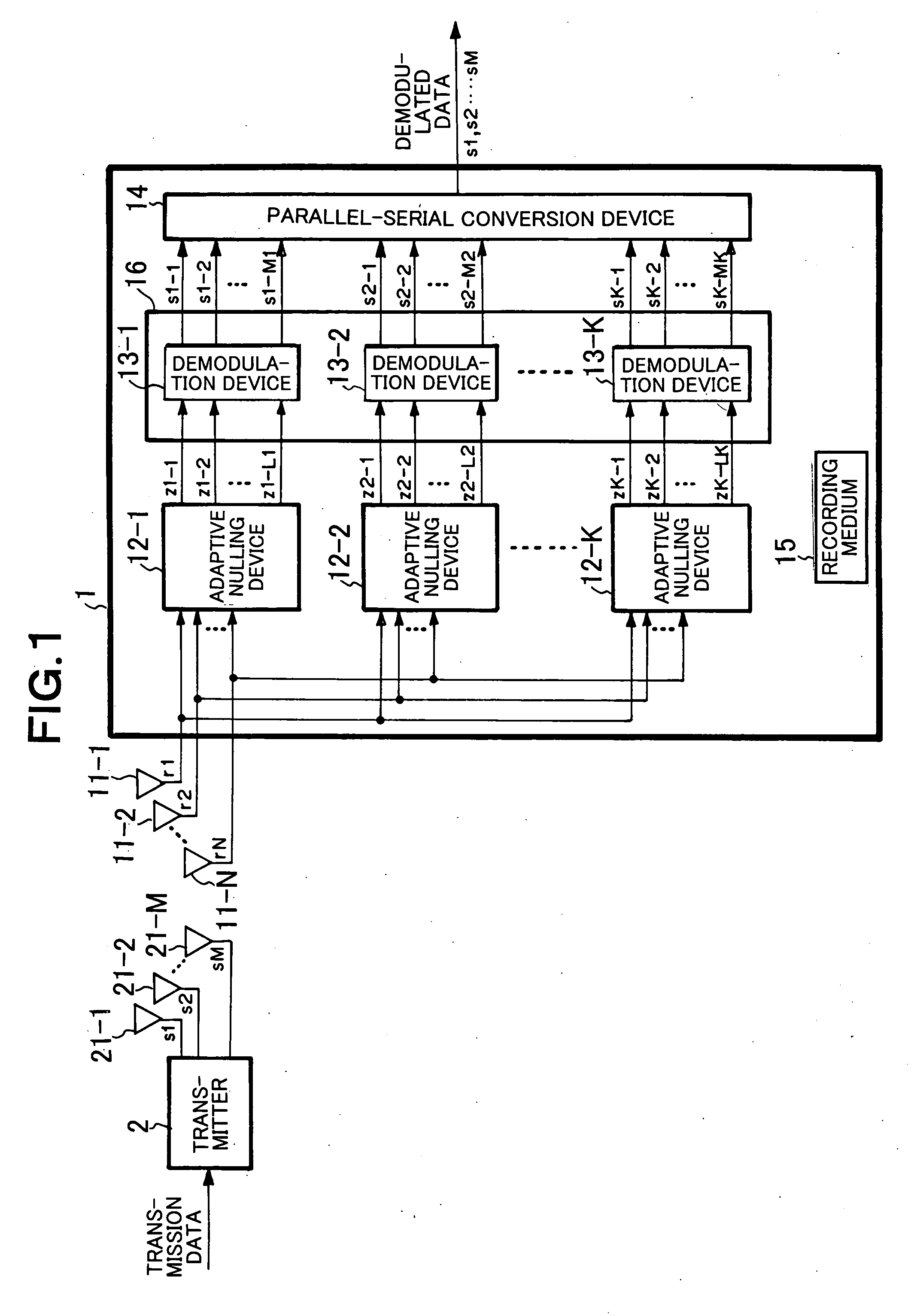
[0058]FIG. 1 is a block diagram showing the structure of the first embodiment of the present invention.

[0059] Referring to FIG. 1, the wireless communication system according to the present embodiment has a structure including a transmitter 2 and a receiver 1. The transmitter 2 generates transmission signals s1 to sM (M is an integer not smaller than 2) from transmission data and transmits the transmission signals s1 to sM through M transmission antennae 21-1 to 21-M. The receiver 1 receives the signals from the transmitter 2 through N reception antennae 11-1 to 11-N (N is an integer not smaller than 2) and demodulates and outputs the received signals r1 to rN.

[0060] The receiver 1 has K adaptive nulling devices 12-1 to 12-K (K is an integer not smaller than 2 and not greater than M), an adaptive demodulation device 16, a parallel-serial conversion device 14, and a recording medium 15. The adaptive nulling devices 12-1 to 12-K are connected to the output sides of the N reception a...

second embodiment

[0070] Next, the second embodiment of the present invention will be described in details with reference to the drawings.

[0071]FIG. 3 is a block diagram showing the structure of the present embodiment. The wireless communication system according to the present embodiment has the same structure as the first embodiment shown in FIG. 1 except that another receiver3 is provided in place of the receiver 1.

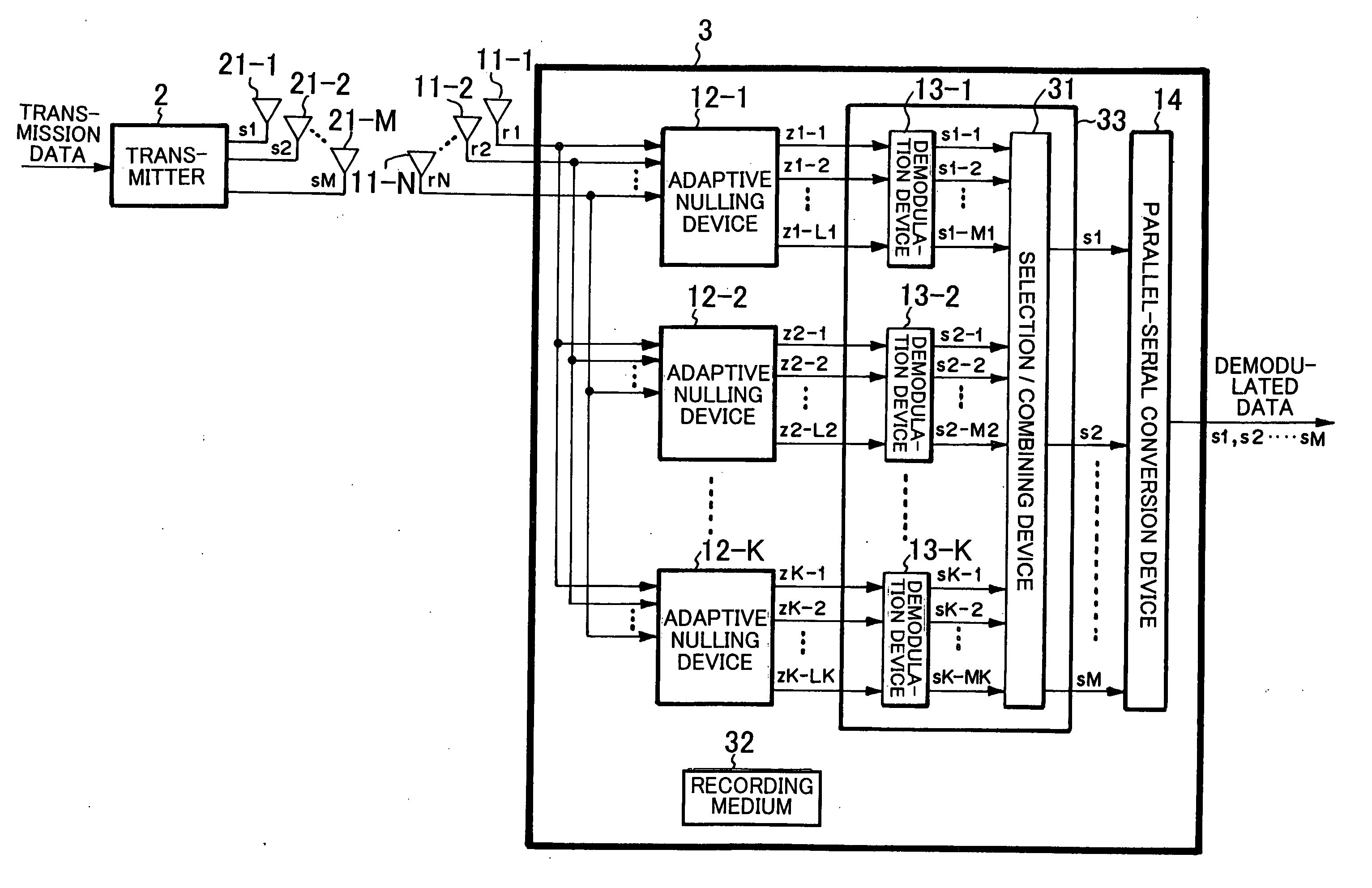
[0072] Referring to FIG. 3, the receiver 3 according to the present embodiment receives transmission signals s1 to sM based on transmission data, which are transmitted through M transmission antennae 21-1 to 21-M from the transmitter 2, through N reception antennae 11-1 to 11-N. The receiver 3 demodulates and outputs the received signals r1 to rN. This receiver 3 has K adaptive nulling devices 12-1 to 12-K (K is an integer not smaller than 2 and not greater than M), an adaptive demodulation device 33, a parallel-serial conversion device 14, and a recording medium 32. The adaptive nulli...

third embodiment

[0079] Next, the third embodiment of the present invention will be described in details with reference to the drawings.

[0080]FIG. 5 is a block diagram showing the structure of the present embodiment. The wireless communication system according to the present embodiment has the same structure as the first embodiment shown in FIG. 1 except that another receiver 4 is provided in place of the receiver 1.

[0081] Referring to FIG. 5, the receiver 4 according to the present embodiment receives transmission signals s1 to sM transmitted through M transmission antennae 21-1 to 21-M from the transmitter 2, through N reception antennae 11-1 to 11-N. The receiver 4 demodulates and outputs the received signals r1 to rN. This receiver 4 has K adaptive nulling devices 12-1 to 12-K, an adaptive demodulation device 45, a parallel-serial conversion device 14, and a recording medium 44. The adaptive nulling devices 12-1 to 12-K are connected to the output sides of the N reception antennae 11-1 to 11-N...


PUM


Abstract

In a wireless communication system having a receiver which receives, through plural reception antennae, signals transmitted from plural transmission antennae, bit likelihood can be surely calculated without requiring a selection processing. A transmitter has M transmission antennae, and transmits signals through the transmission antennae, respectively. A receiver has N reception antennae, and receives signals. K nulling devices perform nulling with use of signals received, and output part of nulling signals. K demodulation devices are inputted with nulling signals, demodulate signals, and output demodulated signals. A parallel-serial conversion device is inputted with demodulated signals, converts the parallel format thereof into a serial format, and outputs the result as demodulated data.

Description

BACKGROUND OF THE INVENTION [0001] 1. Field of the Invention [0002] The present invention relates to a wireless communication system, a receiver, a demodulation method used in the system and receiver, and a program thereof, and particularly to a demodulation method in a receiver in a wireless communication system using plural transmission / reception antennae. [0003] 2. Description of the Related Art [0004] In a wireless communication system in which a signal transmitted from a transmitter having plural transmission antennae is received by a receiver have plural reception antennae, studies have been made of a lot of techniques to reduce the scale of calculation in the receiver. With reference to FIG. 19, a description will now be made of a scheme according to a non-patent document 1 (Jiang Yue, Kyeong Jin Kim; Gibson, J. D.; Iltis, R. A., “Channel Estimation and Data Detection for MIMO-OFDM Systems,” In Proc. Of IEEE Intl. Conf. On Global Telecommunications Conference, Vol. 2, pp. 581...

Claims


Application Information

Patent Timeline
Patent Type & Authority Applications(United States)
IPC IPC(8): H04L1/02H04J99/00
CPCH04B7/0854H04B7/0868H04L1/06H04L25/0204H04L25/0246H04L25/03216H04L25/03318
Inventor ITO, TAKUMI
Owner NEC CORP
Why Eureka
Try Eureka