Liquid-detecting device and liquid container with the same

a liquid detection and liquid container technology, applied in printing and other directions, can solve the problems of limited detection range, ink consumption problem, and limited ink type, so as to prevent the generation of cracks in the piezoelectric layer, detect easily and surely

Inactive Publication Date: 2006-08-03
SEIKO EPSON CORP
View PDF10 Cites 7 Cited by
  • Summary
  • Abstract
  • Description
  • Claims
  • Application Information

AI Technical Summary

Benefits of technology

[0061] According to the liquid-detecting device of the present invention having the aforementioned constitution and the liquid container having the liquid-detecting device, changes in the residual vibration state of the vibration part of the liquid-detecting

Problems solved by technology

However, the method for totalizing the jet count and ink amount of ink drops by the software and calculating the ink consumption has a problem as indicated below.
Therefore, a problem arises that in some individual, the margin of ink may be left over.
However, the detection of the ink level depends on the conductivity of ink, so that there are defects that the kind of detectable ink is limited and the seal structure of the electrode is complicated.
Further, as a material of the electrode, a noble metal which is conductive and corrosion resistant is generally used, so that the manufacturing cost of ink cartridges is increased.
Furthermore, two electrodes must be mounted, so that the manufacturing steps are increased and as a result, the manufacturing cost is increased.
However, in the aforementioned conventional liquid-detecting device (piezoelectric device), there are

Method used


Image

  • Liquid-detecting device and liquid container with the same
  • Liquid-detecting device and liquid container with the same
  • Liquid-detecting device and liquid container with the same

Examples


Embodiment Construction

[0088] Hereinafter, a liquid-detecting device of an embodiment of the present invention and an ink cartridge (a liquid container) having the liquid-detecting device will be explained with reference to the accompanying drawings.

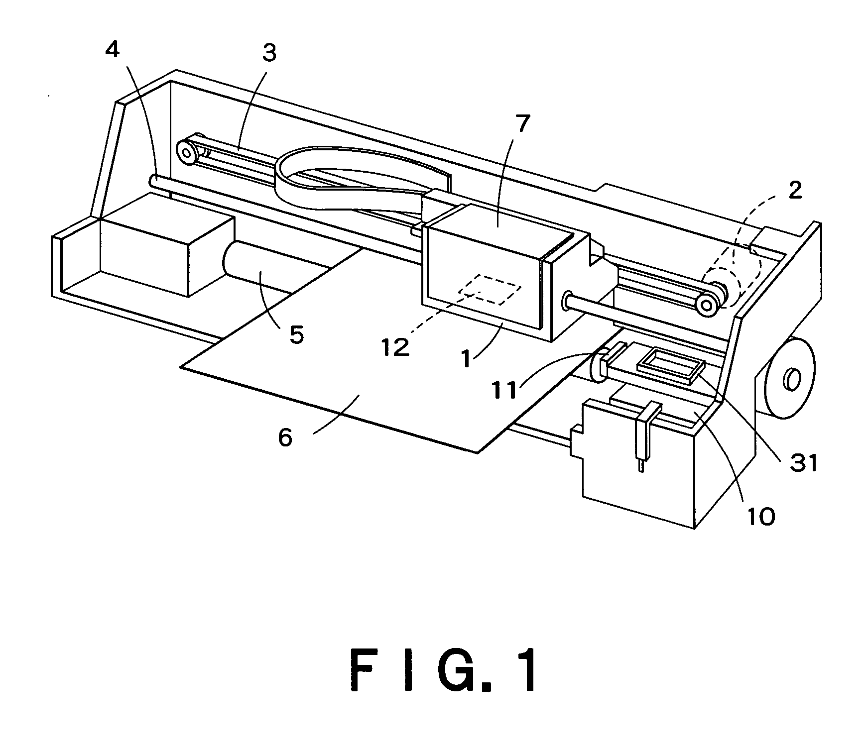
[0089]FIG. 1 shows a schematic constitution of an ink jet recording apparatus (a liquid ejecting apparatus) using the ink cartridge of this embodiment, and in FIG. 1, numeral 1 indicates a carriage, and the carriage 1 is structured so as to be guided by a guide member 4 via a timing belt 3 driven by a carriage motor 2 and move back and forth in the axial direction of a platen 5.

[0090] On the side of the carriage 1 opposite to a recording form 6, an ink jet recording head 12 is loaded and above it, an ink cartridge 7 for feeding ink to the recording head 12 is mounted removably.

[0091] In the home position (on the right of the drawing) which is a non-printing area of the recording apparatus, a cap member 31 is arranged and the cap member 31 is structured, whe...


PUM


Abstract

A first electrode (46) has a main portion (46a) covering almost the overall area of a concavity (43) and including a notch (46c). A piezoelectric layer (47) has a main portion (47a) in a diameter smaller than that of the concavity (43), and the whole thereof is within the concavity area, and almost overall the main portion (47a) excluding the part corresponding to the notch (46c) is laminated on the first electrode (46). An auxiliary electrode (48) extends from the outside of the concavity area into the inside thereof and a part thereof is positioned within the notch (46c) of the first electrode (46) and supports a part of the piezoelectric layer (47). A second electrode (49) has a main portion (49a) laminated on the piezoelectric layer (47) and an extension part (49b) which extends from there and is connected to the auxiliary electrode (48) within the concavity area. The residual vibration state of a vibration part of a liquid-detecting device can be detected easily and surely, and generation of cracks in the piezoelectric layer can be prevented.

Description

TECHNICAL FIELD [0001] The present invention relates to a liquid-detecting device and a liquid container having the liquid-detecting device, and more particularly to a liquid-detecting device and a liquid container having the liquid-detecting device suitable for detection of a liquid residue of a liquid ejecting apparatus. BACKGROUND ART [0002] As a typical example of a conventional liquid ejecting apparatus, there is an ink jet recording apparatus having an ink jet recording head for image recording. As other liquid ejecting apparatuses, for example, an apparatus having a coloring material ejecting head used to manufacture color filters such as a liquid crystal display, an apparatus having an electrode material (conductive paste) ejecting head used to form electrodes such as an organic EL display and a face emission display, an apparatus having a biological organic substance ejecting head used to manufacture biological chips, and an apparatus having a sample ejecting head as a prec...

Claims


Application Information

Patent Timeline
IPC IPC(8): B41J2/195B41J2/175
CPCB41J2/17566B41J2002/17583
Inventor TAKAHASHI, TOMOAKIKATAKURA, TAKAHIROSHINADA, SATOSHI
Owner SEIKO EPSON CORP
Why Eureka
Try Eureka