Pneumatic tire

a technology of pneumatic tires and lateral force, which is applied in the direction of non-skid devices, vehicle components, transportation and packaging, etc., can solve the problems of uneven wear such as heel and toe wear, block rigidity deterioration, and wall surfaces that cannot support each other against lateral force, and achieve excellent uneven wear resistance.

Inactive Publication Date: 2005-09-29
SUMITOMO RUBBER IND LTD
View PDF9 Cites 22 Cited by
  • Summary
  • Abstract
  • Description
  • Claims
  • Application Information

AI Technical Summary

Benefits of technology

[0007] Thereupon, it is an object of the present invention to provide a pneumatic tire in which a tie bar is provided with a three-dimensional sipeing in which sipeing wall surface is repeatedly recessed and projected three-dimensionally, excellent uneven wear resistance can be exhibited, on-snow performance and wet performance can highly be secured from the middle stage of wear, and crack can be prevented from being generated from the sipeing bottom.

Problems solved by technology

On the other hand, the block rigidity is deteriorated, and uneven wear such as heel and toe wear is prone to be generated.
However, in a normal sipeing, although the wall surfaces support each other against the force in the circumferential direction of the tire and thus the block rigidity can highly be secured, the wall surfaces can not support each other against the lateral force, and large distortion is generated in the bottom of the sipeing.
If the distortion is repeatedly generated, the crack is prone to be generated in the sipeing bottom, and there is a tendency that block becomes cracked.

Method used


Image

  • Pneumatic tire
  • Pneumatic tire
  • Pneumatic tire

Examples


examples

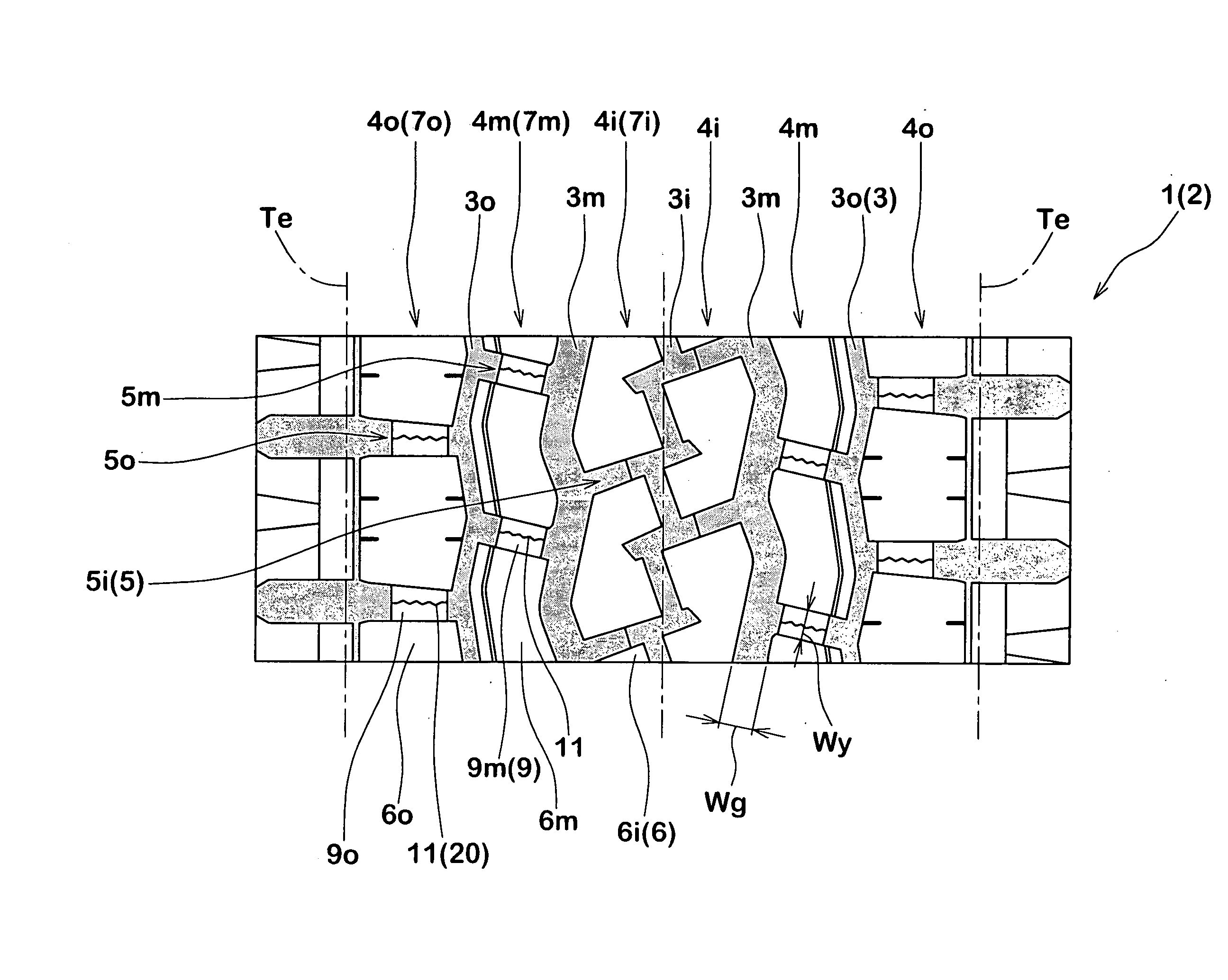
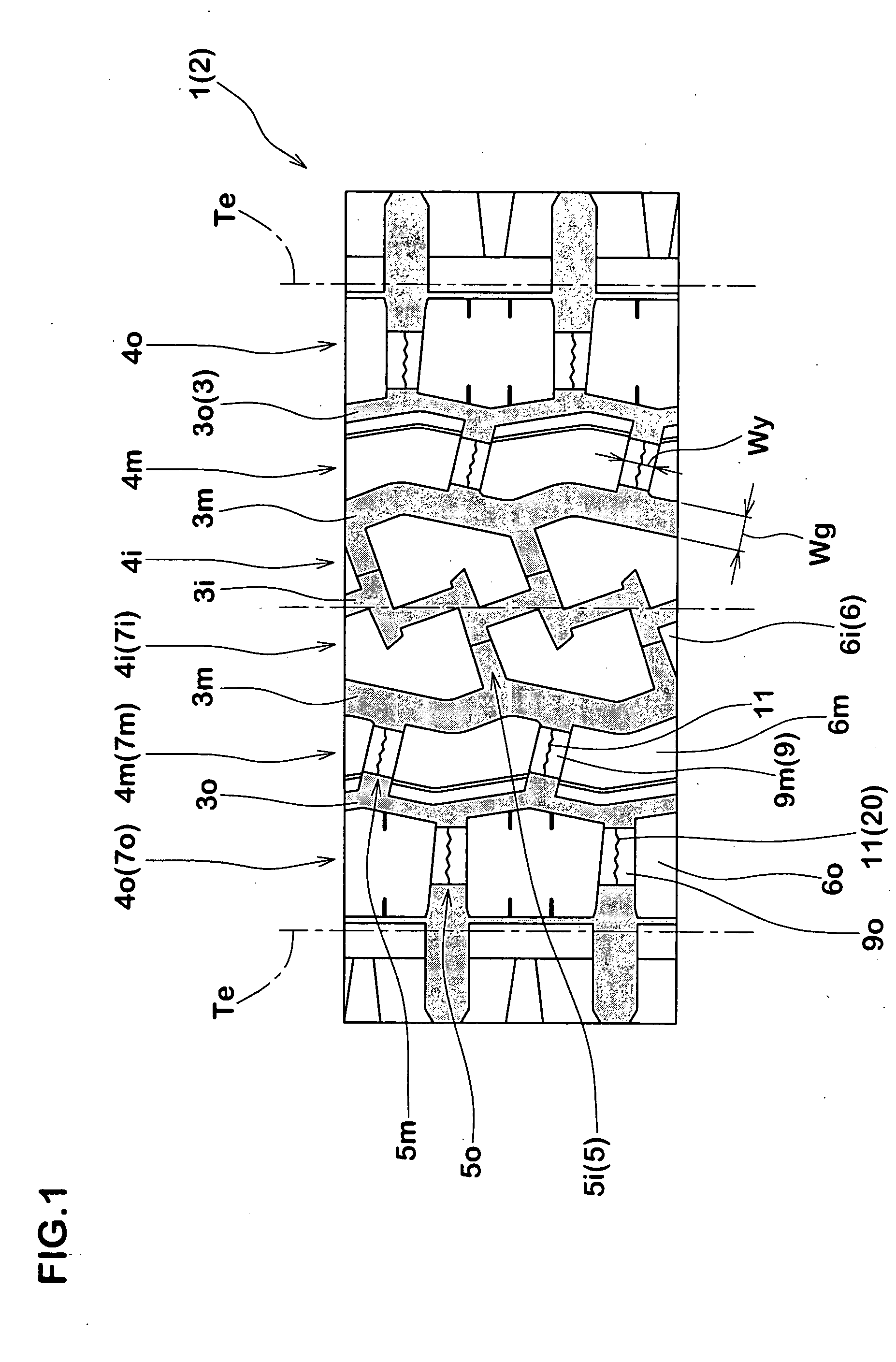
[0045] Based on the tread pattern shown in FIG. 1, heavy load radial tires (tire size: 11R22.5-14PR) each having a tie bar provided with a sipeing of a specification shown in Table 1 were prototyped. Wet performance and a crack generation state in the sipeing bottom were tested for a new prototyped tire and 50% worn tire. Specifications of the tires other than sipeing were the same.

[0046] (1) Wet Performance:

[0047] The prototyped tires were mounted on all wheels of a 2-D.4 test vehicle (having an anti-lock brake system) under conditions of rim (7.50×22.5) and internal pressure (850 kPa). The vehicle was allowed to run on a wet road in a state in which a constant load (ten tons) was applied, and a braking distance required until the vehicle stopped after applying abrupt brake from 60 km / h was measured. Reciprocals of measured values are indicated with indices while a comparative example 1 is defined as 100. This test was carried out for the new tire and the 50% worn tire. The great...


PUM


Abstract

A pneumatic tire includes a tie bar 9 in a lateral groove 5 disposed in a block array 7. The tie bar 9 connects adjacent blocks 6 in a circumferential direction through the lateral groove 5. The tie bar 9 is formed with a sipeing 11 having a zigzag portion 13. The zigzag portion 13 extends in a zigzag manner in a direction of a groove centerline of the lateral groove 5. The sipeing 11 comprises a three-dimensional sipeing 20 in which a sipeing wall surface 11S is repeatedly recessed and projected three-dimensionally.

Description

BACKGROUND OF THE INVENTION [0001] 1. Field of the Invention [0002] The present invention relates to a pneumatic tire in which a tie bar is provided with a sipeing to enhance on-snow performance and wet performance from middle stage of wear while securing uneven-wear resistance. [0003] 2. Description of the Related Art [0004] In a tire such as an all-season tire and snow tire, there is employed a block pattern in which a tread portion is divided into a plurality of blocks by tread grooves including circumferential main grooves extending in the circumferential direction of the tire and lateral grooves intersecting with the circumferential main grooves while taking on-snow performance and wet performance into consideration. At that time, if a tread groove is formed deeply and widely, the performance such as the on-snow performance can highly be secured. On the other hand, the block rigidity is deteriorated, and uneven wear such as heel and toe wear is prone to be generated. [0005] Jap...

Claims


Application Information

Patent Timeline
Patent Type & Authority Applications(United States)
IPC IPC(8): B60C11/03B60C11/11B60C11/12B60C11/13
CPCB60C11/11B60C11/12B60C11/1369Y10S152/902B60C2011/1213B60C11/124Y10S152/03B60C11/1218
Inventor SHINMURA, YASUSHISUGIHARA, HIDEAKI
Owner SUMITOMO RUBBER IND LTD
Why Eureka
Try Eureka