Collimating lens structures

Inactive Publication Date: 2006-08-03
AVAGO TECH INT SALES PTE LTD
View PDF5 Cites 11 Cited by
  • Summary
  • Abstract
  • Description
  • Claims
  • Application Information

AI Technical Summary

Problems solved by technology

Unfortunately, these two prior art approaches suffer from several drawbacks or disadvantages.
First, in compact space-limited applications, such as an optical mouse product, the prior art collimators consume too much sp

Method used


Image

  • Collimating lens structures
  • Collimating lens structures
  • Collimating lens structures

Examples


Embodiment Construction

[0018] Collimating lens structures with tilted output beam are described. In the following description, for the purposes of explanation, numerous specific details are set forth in order to provide a thorough understanding of the present invention. It will be apparent, however, to one skilled in the art that the present invention may be practiced without these specific details. In other instances, well-known structures and devices are shown in block diagram form in order to avoid unnecessarily obscuring the present invention.

Collimator Lens Structure

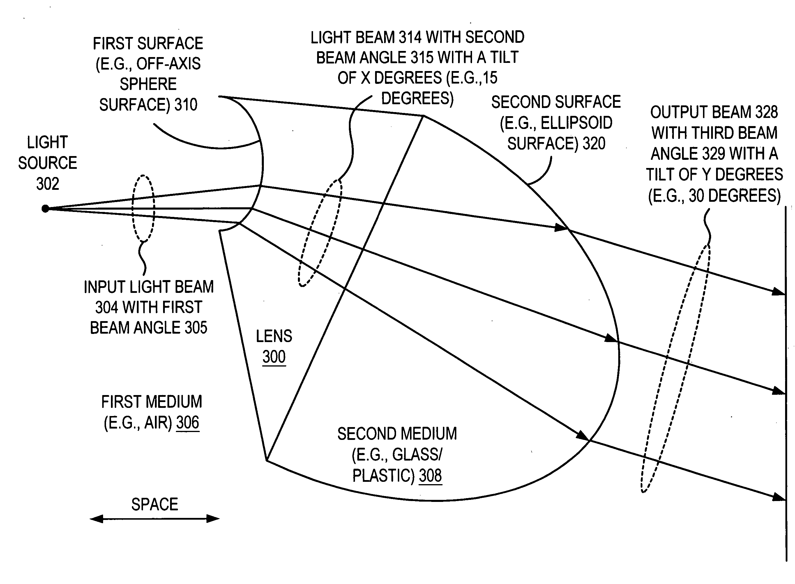
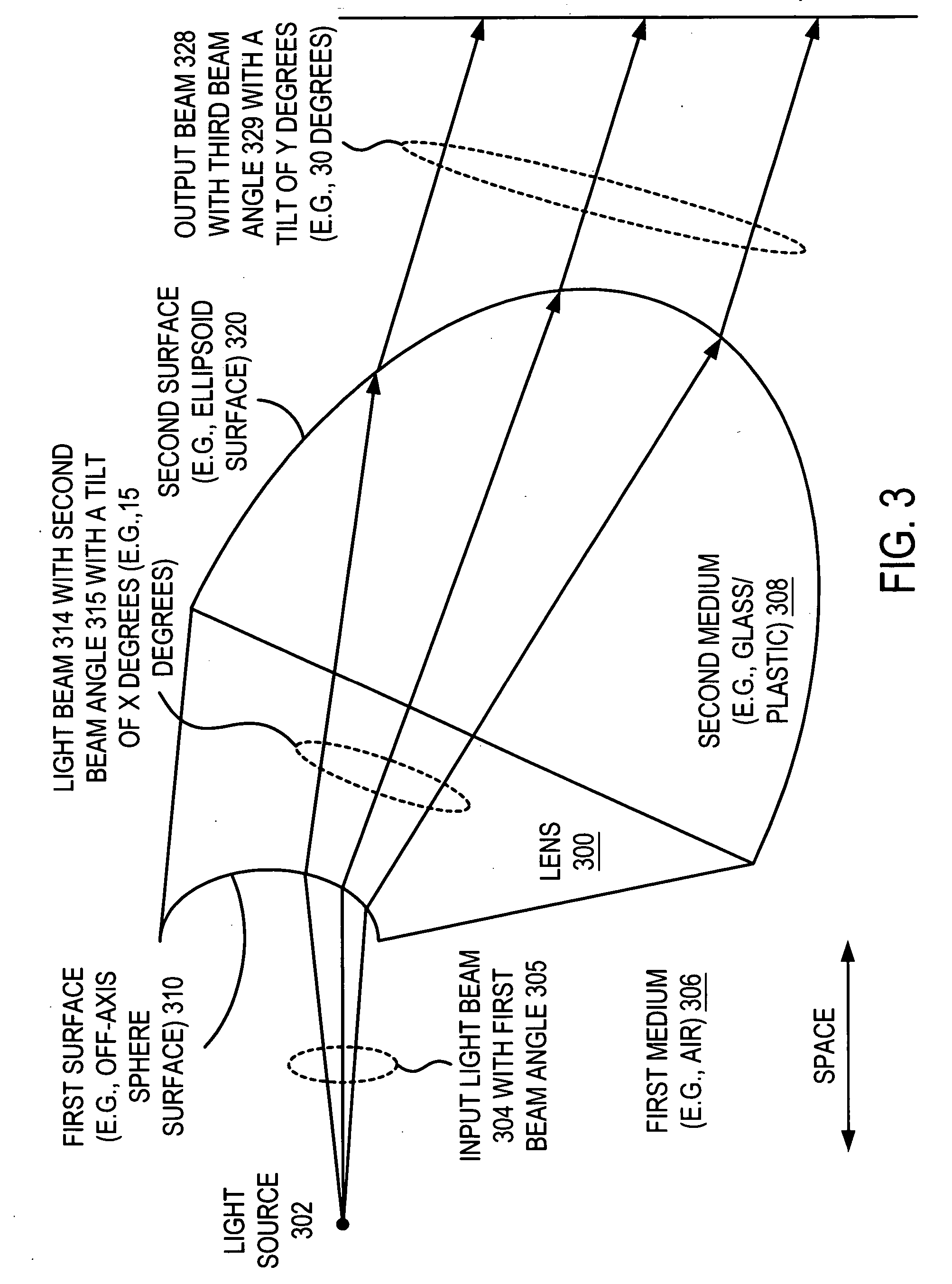
[0019]FIG. 3 illustrates an optic element 300 according to one embodiment of the present invention. A light source 302 that generates a light beam 304 (also referred to herein as an “input light beam 304”) with a first beam angle 305 is provided. The light source 302 can be, for example, a laser or a light emitting diode (LED). The light source 302 directs the light beam 304 with the predetermined beam angle 305 along a predetermined a...


PUM


Abstract

An optic element receives an input light beam with a first beam angle and an axis. The optic element includes a first surface that receives the input light beam and generates an expanded light beam with a second beam angle that is greater than or equal to the first beam angle. The optic element includes a second surface that receives the expanded light beam and generates an output light beam that is either substantially collimated or near collimated. The output light beam is tilted a predetermined degrees with respect to the axis of the input light beam.

Description

FIELD OF THE INVENTION [0001] The present invention relates generally to collimating lens structures, and more particularly, to collimating lens structures with tilted output beam that perform beam expansion and collimating. BACKGROUND OF THE INVENTION [0002] Collimator lenses that are formed in glass or plastics are well known. FIG. 1 illustrates a first prior art collimator lens 10. The first prior art collimator lens 10 includes a hyperboloid surface 12 and a plane surface 14. A light source 16, such as a laser, generates a light beam 18 that generally diverges with a beam angle or width. After passing through the prior art lens 10, the light beams 20 are generally parallel. It is noted that the hyperboloid surface 12 performs the collimating function. [0003]FIG. 2 illustrates a second prior art collimator lens 30. The second prior art collimator lens 30 includes a plane surface 32 and a convex surface 34. A light source 36, such as a laser, generates a light beam 38 that general...

Claims


Application Information

Patent Timeline
IPC IPC(8): G02B3/02
CPCG02B27/30G06F3/0317G02B3/04G02B3/00
Inventor SMITH, GEORGE E.XIE, TONG
Owner AVAGO TECH INT SALES PTE LTD
Why Eureka
Try Eureka