
Terminal fitting and a connector provided therewith

a technology of connecting rods and connectors, which is applied in the manufacture of contact members, coupling contact members, coupling device connections, etc., can solve the problems of weaker projection and less effective projection, and achieve the effect of preventing entanglemen

Active Publication Date: 2006-08-03
SUMITOMO WIRING SYST LTD
View PDF5 Cites 2 Cited by
  • Summary
  • Abstract
  • Description
  • Claims
  • Application Information

AI Technical Summary

Benefits of technology

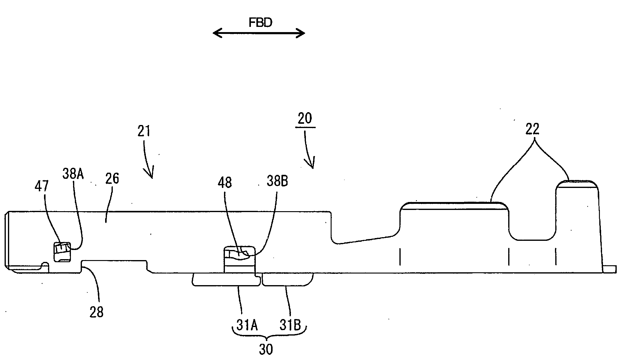
[0007] The invention relates to a terminal fitting with a tubular main portion that can be inserted into a cavity of a connector housing. At least one stabilizer is formed by making at least one cut in the main portion and bending the cut area. The cutting and bending to form the stabilizer creates a hole in the main portion. An inner wall is provided at an inner side near the hole left in the main portion and at least partly closes the hole. Thus, external matter cannot intrude through the hole and into the main portion. Accordingly, a resilient contact in the main portion is not at risk of being plastically deformed by contact with external matter. Further, a tab or stabilizer of one terminal fitting cannot engage in a hole of another terminal fitting. Thus, entanglement is prevented regardless of whether the terminal fittings are female terminal fittings or male terminal fittings.
[0008] The main portion preferably is a substantially polygonal tube and a resilient contact is formed in the main portion. At least one projection bulges from a side edge of the resilient contact substantially facing an inner wall of the main portion. The inner wall has at least one preventing portion for engaging the projection and preventing excessive displacement of the resilient contact. The preventing portion also preferably is disposed to close the hole left in the main portion. Thus, the state of the projection of the resilient contact can be confirmed visually from the outside through the hole.
[0009] The widthwise center of the resilient contact preferably is offset from the widthwise center of the main portion towards a side opposite the inner wall. The offset disposition of the resilient contact would require a longer projection for preventing excessive displacement if no inner wall was provided. A longer projection could be weaker and less effective. However, the presence of the inner wall enables the projection to be shorter and hence stronger.
[0013] One or more preventing portions preferably are provided in the main portion and contact the resilient piece for preventing damage when the resilient contact piece is deflected in a direction other than the deflection direction caused by the mating male terminal fitting inserted into the main portion.

Problems solved by technology

Further, a tab or stabilizer of one terminal fitting cannot engage in a hole of another terminal fitting.
A longer projection could be weaker and less effective.

Method used


Image

  • Terminal fitting and a connector provided therewith
  • Terminal fitting and a connector provided therewith
  • Terminal fitting and a connector provided therewith

Examples


Embodiment Construction

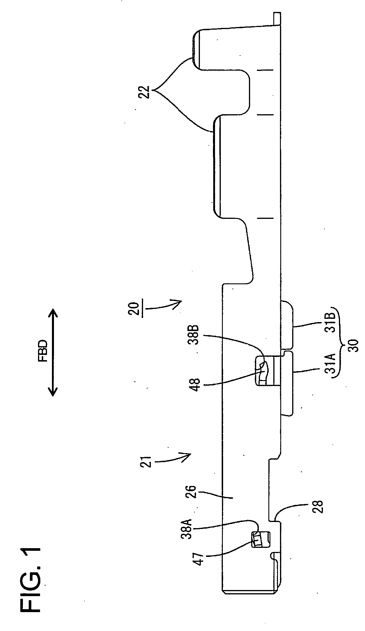
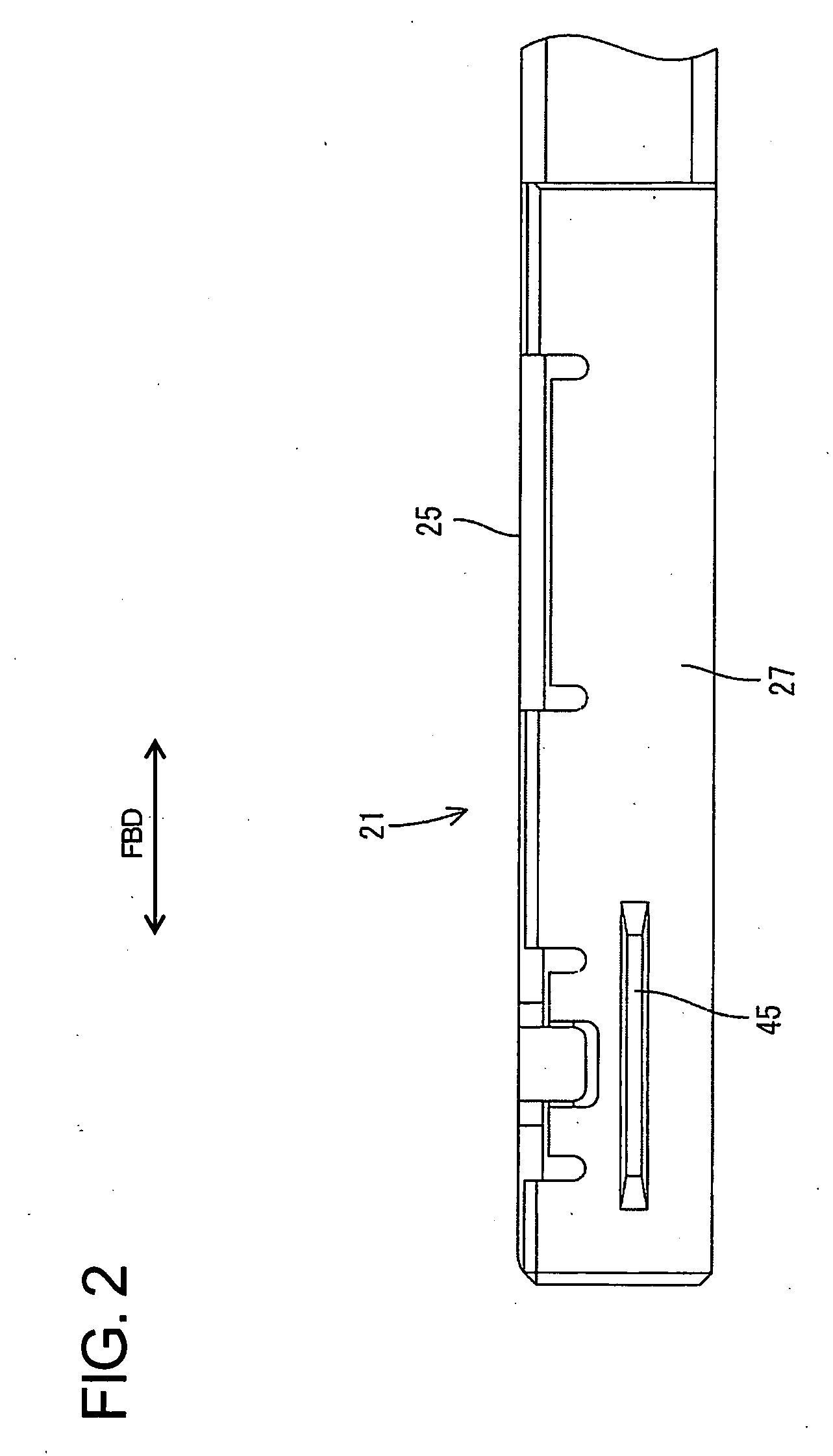
[0028] A female terminal fitting according to the invention is identified by the numeral 20 in FIGS. 1 to 12. A plurality of such female terminal fittings may be inserted into a connector housing 10 shown in FIGS. 11 and 12. The housing 10 is made e.g. of a synthetic resin and cavities 11 penetrate the housing 10 in forward and backward directions FBD. A lock 12 is cantilevered forwardly along the bottom wall of each cavity 11. Further, a guide groove 13 extends substantially in forward and backward directions FBD near the right side of the bottom wall of the cavity 11 when viewed from behind. The guide groove 13 extends from the rear entrance of the cavity 11 to a position near the base end of the lock 12.

[0029] A retainer 15 for doubly locking the female terminal fittings 20 is mounted into an upper side of the housing 10 in FIG. 11, and a front plate 17 is to mounted on the front surface of the housing 10. Tabs 51 of male terminal fittings 50 mounted in an unillustrated mating m...


PUM


Abstract

A stabilizer (30) is divided into a front stabilizer (31A) and a rear stabilizer (31B) with a small clearance therebetween. The front and rear stabilizers (31A, 31B) are formed from a left side plate (25) and a bottom plate (25) of a main portion (21) by cutting and bending while leaving holes (32A, 32B). The side hole (32A) is relatively larger and exposes a free end (40A) of a resilient contact (40) to the outside. Thus, a rear inner plate (36) is arranged at an inner side of the side hole (32A) to close the side hole (32A). The plastic deformation of a side of the resilient contact (40) towards the free end (40A) is prevented by preventing the intrusion of a tab (51) of a male terminal fitting (50) or other external matters through the side hole (32A).

Description

BACKGROUND OF THE INVENTION [0001] 1. Field of the Invention [0002] The invention relates to a terminal fitting with at least one stabilizer and to a connector provided with such a terminal. [0003] 2. Description of the Related Art [0004] Japanese Unexamined Patent Publication No. H05-190227 discloses a female terminal fitting that has a rectangular tubular main portion and a resilient contact inside the main portion. The terminal fitting is secured to an end of a wire and then is inserted from behind into a cavity formed in a housing. A stabilizer projects from a side surface of the main portion and is received in a guide groove of the cavity. The stabilizer and guide groove prevent an erroneous (e.g. upside down) insertion of the terminal fitting into the cavity and stably guide the terminal fitting into the cavity. [0005] The above-described stabilizer is formed by making a cut in a side wall of the main portion and bending the cut area. This cutting and bending leaves an opening...

Claims


Application Information

Patent Timeline
Patent Type & Authority Applications(United States)
IPC IPC(8): H01R13/187
CPCH01R13/113H01R13/422H01R43/16
Inventor KOBAYASHI, YUTAKAKAWASE, HAJIMENORO, YUTAKA
Owner SUMITOMO WIRING SYST LTD
Learn More