Al technical title is built by PatSnap Al team. It summarizes the technical point description of the patent document.
a ratchet buckle and adjustable technology, applied in the direction of fastenings, garment fasteners, press-button fasteners, etc., can solve the problems of difficulty in adjusting the tension of the strap, the patient's difficulty in refastening the strap exactly, and the wear of the hook and loop fasteners
Inactive Publication Date: 2006-08-10
MEDICAL TECH
View PDF6 Cites 30 Cited by
Summary
Abstract
Description
Claims
Application Information
AI Technical Summary
This helps you quickly interpret patents by identifying the three key elements:
Problems solved by technology
Method used
Benefits of technology
[0009] The invention relates to an adjustable fastener such as one suitable for use in securing straps in a variety of orthotic and other types of devices. The fastener comprises a male portion and a female portion that are each attached to a strap or other desired location on the device with which the fastener is used. The male portion comprises an elongated tab and the female portion comprises a housing and a passage through the housing. The passage allows the elongated tab to slide through the housing in the female portion. An engagement finger in the housing is resi...
Problems solved by technology
Not all types of fasteners are appropriate for any given particular application.
While this type of fastener makes it easy for a patient to undo the straps to remove the brace when it is not needed, it can be difficult for the patient to refasten the strap with the exact amount of tension that was present when the strap was removed.
In addition, hook and loop fasteners tend to wear out over time, especially when they are frequently opened and closed as would occur when a brace is removed daily for such activities as bathing, physical therapy, and/or sleeping.
While snap fasteners are mo...
Method used
Image
Click on the blue label to locate the original text in one second.
Reading with bidirectional positioning of images and text.
Examples
Embodiment Construction
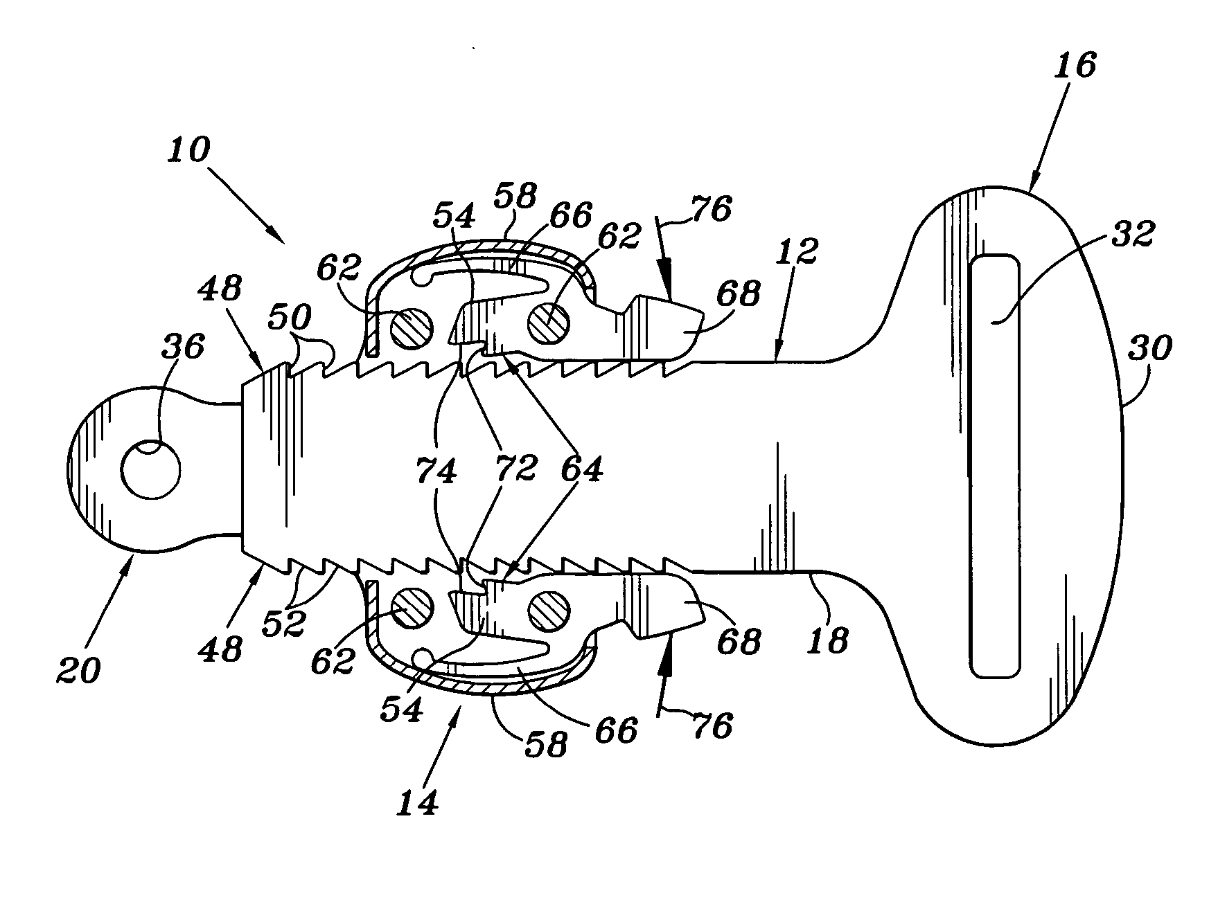
[0018] The following description will describe the structure and function of the claimed fastener in terms of the preferred embodiments. In discussing the various embodiments of the current invention, corresponding structure will be identified using the same reference numerals. Preferably the parts of the fastener are formed from a polymeric material and most preferably from ST801 Nylon, however those of skill will recognize that many other materials can be appropriate for use in all or portions of the disclosed fastener. Various parts may include up to about 13% glass fibers in the ST801 Nylon, which improves its stiffness and dimensional stability. The inclusion of glass fibers is especially desirable for engagement fingers 54 and leaf springs 66 to help provide the desired strength and spring tension.
[0019] Those of skill in the art will recognize the many purposes for which the fastener of the current invention can be used. Preferably, the fastener is adapted for use in securin...
PUM
Abstract
The invention relates to an adjustable fastener such as one suitable for use in securing straps in a variety of orthotic and other types of devices. The fastener comprises a male portion and a female portion that are each attached to a strap or other desired location on the device with which the fastener is used. The male portion comprises an elongated tab and the female portion comprises a housing and a passage through the housing. The passage allows the elongated tab to slide through the housing in the female portion. An engagement finger in the housing is resiliently biased to engage one or more teeth along an edge of the elongated tab to prevent the elongated tab from sliding further out of the passage. The finger can be selectively disengaged from the teeth to allow the elongated tab to slide further or completely out of the housing. Preferably there are teeth along both edges of the elongated tab and there is a finger in the housing adapted to separately engage each set of teeth. It is additionally preferable that the elongated tab can be ratcheted further into the housing by sliding it without disengaging the engagement finger.
Description
BACKGROUND OF THE INVENTION [0001] 1. Field of the Invention [0002] This invention relates generally to an adjustable fastener and, more particularly, to an adjustable fastener that can be used to secure the end of a brace strap. [0003] 2. Description of Related Art [0004] Various types of buckles, clips, and other connectors that can be used in various orthotic and other types of devices such as to secure one end of a strap either to another portion of the same strap or to some other anchor point in the device are known to those of skill in the art. Some examples of previously disclosed buckles include those described in U.S. Pat. No. 3,112,496; U.S. Pat. No. 3,808,643; U.S. Pat. No. 3,827,107; U.S. Pat. No. 4,005,506; U.S. Pat. No. 4,310,110; U.S. Pat. No. 4,378,793; U.S. Pat. No. 5,201,100; U.S. Pat. No. 5,548,871; U.S. Pat. No. 5,502,843; U.S. Pat. No. 6,131,249; U.S. Pat. No. 6,163,941; U.S. Pat. No. 6,360,410; U.S. Pat. No. 6,631,537; U.S. Pat. No. 6,748,630; U.S. Pat. No. 6,7...
Claims
Application Information
Patent Timeline
Application Date:The date an application was filed.
Publication Date:The date a patent or application was officially published.
First Publication Date:The earliest publication date of a patent with the same application number.
Issue Date:Publication date of the patent grant document.
PCT Entry Date:The Entry date of PCT National Phase.
Estimated Expiry Date:The statutory expiry date of a patent right according to the Patent Law, and it is the longest term of protection that the patent right can achieve without the termination of the patent right due to other reasons(Term extension factor has been taken into account ).
Invalid Date:Actual expiry date is based on effective date or publication date of legal transaction data of invalid patent.